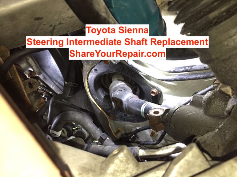
Do you have stiff steering on your Sienna? Do you hear a faint rattle behind the dash when driving down the road? I’ve heard a rattle behind my dash for as long as I’ve owned my 2004 Toyota Sienna. It has always perplexed me. Recently our steering developed a stiff spot, which was hard to turn past. I wrote an article on how to temporarily this problem by spraying lubricant on the u-joint: How to Fix Toyota Sienna Stiff Steering. Now I’m fixing it permanently by replacing the steering intermediate shaft assembly. Here are Toyota Sienna steering intermediate shaft replacement instructions. With my step-by-step instructions you can repair your Sienna too…
Toyota Sienna Steering Intermediate Shaft Replacement
Vehicle:
Parts Required:
- Toyota Sienna Steering Shaft Assembly, Part Number 45220-08042: (Aftermarket, OEM)
- Liquid Wrench Penetrating Oil
Tools Required:
- 10mm, 12mm sockets, 10mm closed-end wrench, Socket ratchet (I used both my 1/4″ and 3/8″ ratchets) — Get all these in this 170-piece tool set
- vehicle ramps
- 13″+ Pry-Bar or Very Large and Long Flat-Head Screwdriver (required for driving off the lower end of the shaft)
Steering Intermediate Shaft Replacement Instructions:
Step 1: Drive the van up on ramps.
I have given detailed instructions on how to pull a van up on ramps in the following article: Toyota Sienna Oil Change. Make sure you are on solid and level ground. I would not put the front end of your van up on jack stands because there is an advantage to having your wheels held in place with the vehicle’s weight so they don’t turn during the repair.
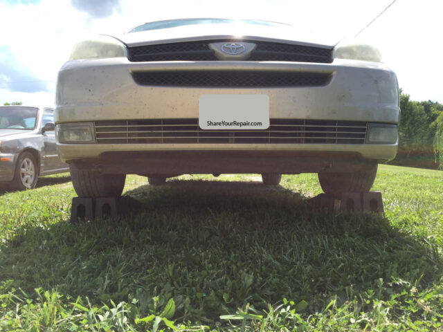
You also want to make sure that your wheels are perfectly straight:
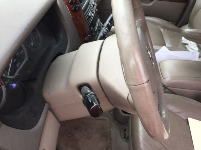
I must add that I tried various means to attempt to hold the steering wheel straight (which you may see in subsequent pictures), including installing wood clamps, which pressed against the seat:
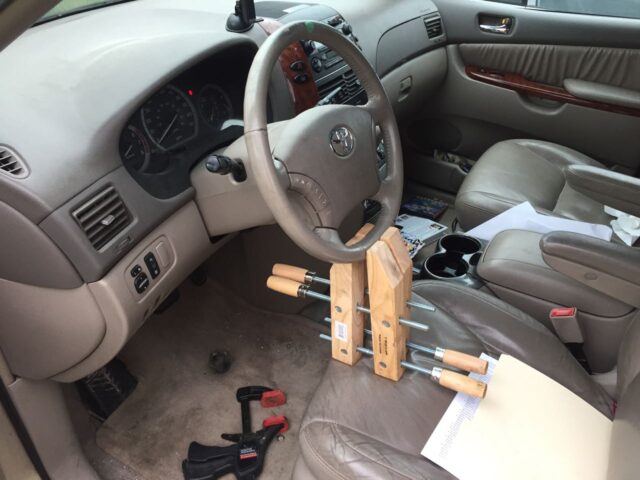
Important: Once you have disconnected your steering wheel, you could spin the wheel and possibly sever the cables that run to the horn and steering wheel controls. Make sure your kid doesn’t jump in the driver’s seat and start spinning the wheel. Also, the van has a sensor that tells the computer how many degrees the wheel has turned–if you turn it a couple times it could possibly throw off the computer.
Step 2: Locate the Steering Intermediate Shaft
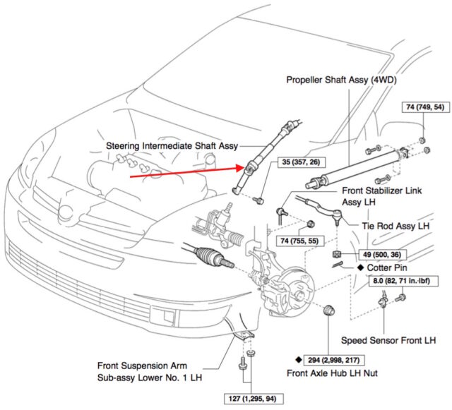
Warning: You will be working around the engine and the exhaust system so do not attempt to proceed with this repair until you have allowed sufficient time for your van to cool off.
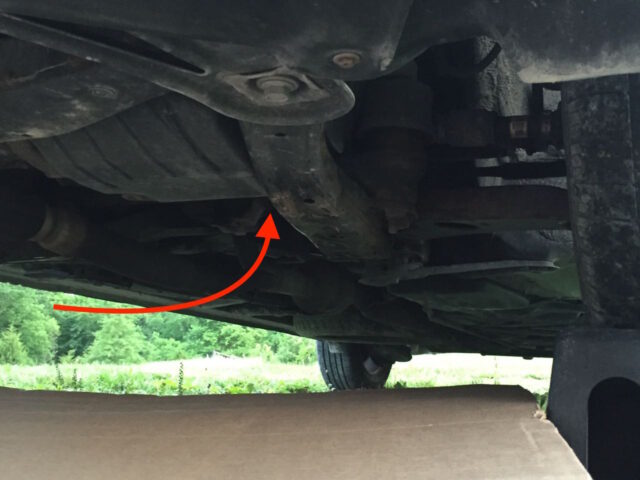
Under the van, the steering intermediate shaft can be located here:
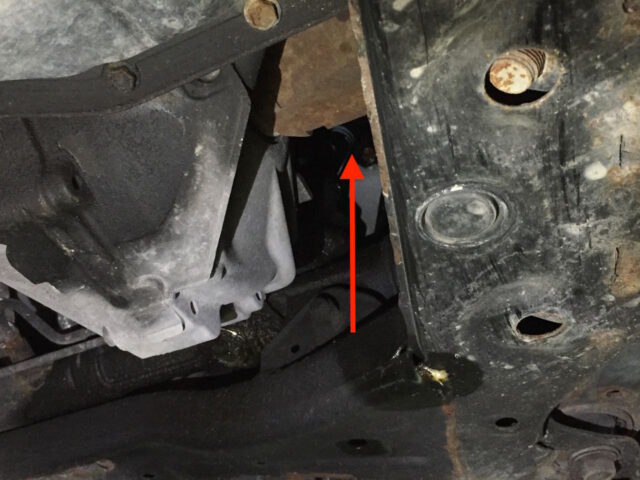
When you look up in the area indicated above, you’ll be able to see the u-joint on the steering intermediate shaft:
Step 3: Spray some penetrating oil on the lower connection.
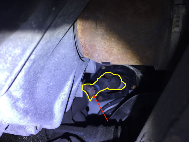
Give yourself a break and spray some penetrating oil on the lower connection to aid in the removal of the shaft:
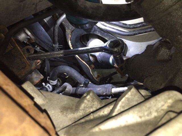
Step 4: Remove the lower 12-mm bolt from the steering intermediate shaft.
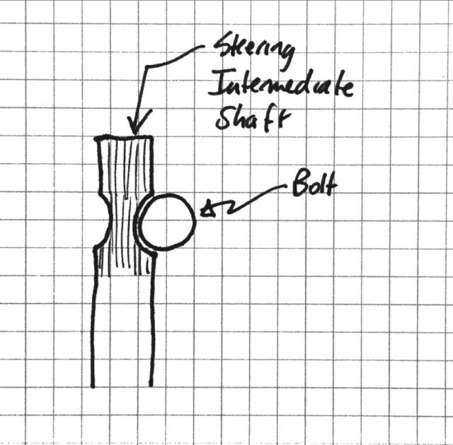
I started on this end of the shaft because I felt it may be the most difficult bolt to remove. If I couldn’t get this bolt loose then I could stop before going too far!! And, since the bolts didn’t come with the part I ordered I knew I was going to need to reuse the bolt–if I couldn’t loosen it, then I knew I needed to stop, at least for now. I only used a 12mm socket and ratchet to reach the bolt. One thing I’d like to mention, which may save someone out there some stress, is that the bolt passes through a groove on the shaft, keeping it from coming out, as I have illustrated below. So you must completely remove the bolt in order to remove the shaft:
I had to put the handle of the ratchet up in the air to be able to have much swing to loosen the bolt. Make sure you have the socket all the way on the bolt head so you don’t accidentally round the bolt. I didn’t have too much problem getting it loose.
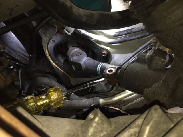
Once I removed the bolt I wanted to make it easier for me to remove the shaft so I attempted to spread the end open with a large flat-head screwdriver, as seen below. I don’t know that this really did any good. I will show you what I think is a sure fire way to get the lower end of the shaft off. In Step 11 I found a way that really makes attempting to pry that open unnecessary (and when you attempt to pry it turns the shaft, which is not helpful).
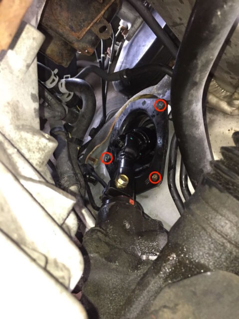
Step 5: Remove the three 10mm bolts from the dust shield.
This may be an optional step but I removed the bolts from this plastic shield in order to give me more room to work the shaft off each end. I was not able to get a socket onto each bolt but had to use a closed-end wrench on at least one of them:
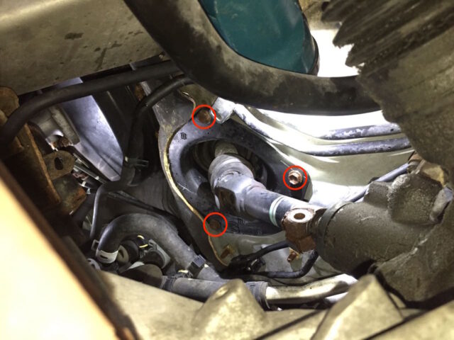
Here is a close up of the dust cover with the bolts removed, somehow I oriented the camera the other way but wider pictures look better:
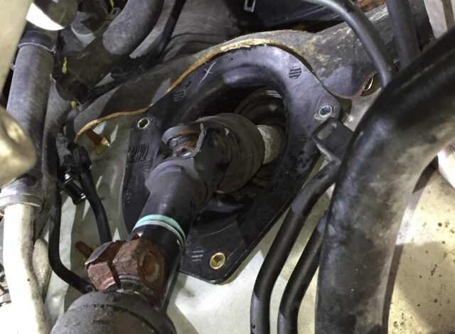
Step 6: Disconnect the battery.
From what I understand, you can avoid some traction control problems by disconnecting the battery when you are working on the steering. If you have not disconnected the battery and the steering wheel is not exactly in the same position it was in previously, then the traction control will have issues. I disconnected the battery at this point. Loosen the 10mm bolt and lift the battery cable off the battery terminal:
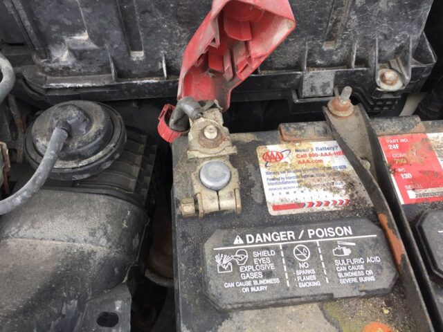
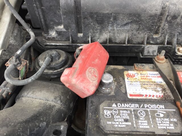
I put the cap over the end of the battery cable to keep it from touching the battery:
Step 7: Remove the lower dash trim.
I found it very helpful to have a more direct shot at the upper bolt of the steering intermediate shaft. You can look up under the dash and decide if you want to remove this trim, so feel free to skip Step 7 if you like. It might seem difficult but it really wasn’t that hard and I actually ended up removing it and reinstalling it a couple times. The goal of this is to gain easy access to the top bolt of the steering intermediate shaft, as viewed from up under the dash:
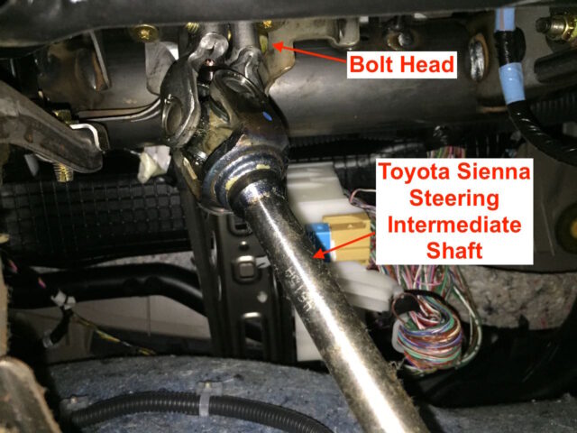
Step 7a: Remove the lower driver door trim piece.
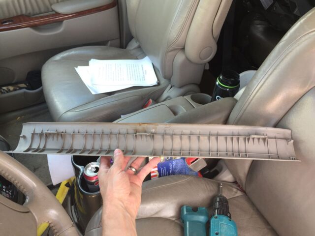
We must remove this piece because it overlaps another piece you need to remove. This trim pops straight up and shouldn’t require any tools–simply get your fingers under the edge along the carpet and pull it straight up.
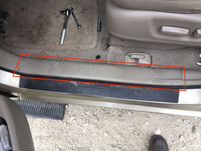
Here’s what the back of the trim piece looks like once removed:
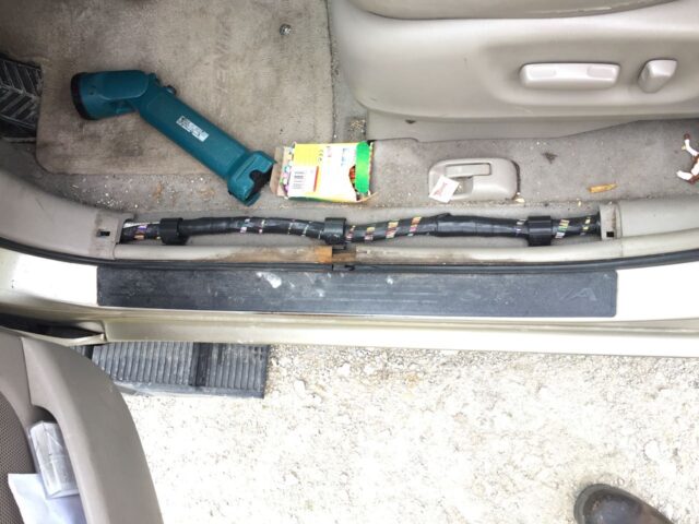
Step 7b: Remove the driver’s side door frame front lower corner trim piece.
There is one plastic nut which you can remove by hand:
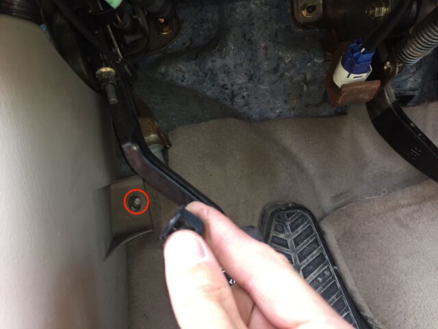
Pull the trim straight off and it will pop off:
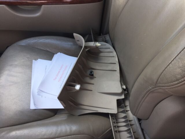
Step 7c: Remove the two 10mm bolts from the lower dash panel:
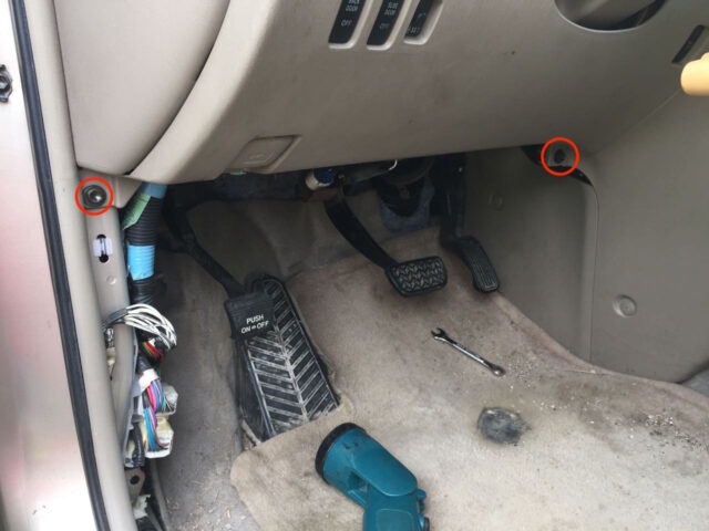
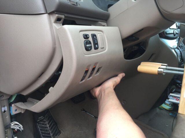
Step 7d: Pop the lower dash panel free.
CAUTION: Be careful because there are many electrical connectors connected to the panel which you will need to disconnect first before the panel will be completely free to remove.
Step 7e: Disconnect the electrical connectors and the hood latch.
There are 6 electrical connectors on the left and 1 on the right and one cable on the lower left. There is a button that must be pushed in on the side of each electrical connector:
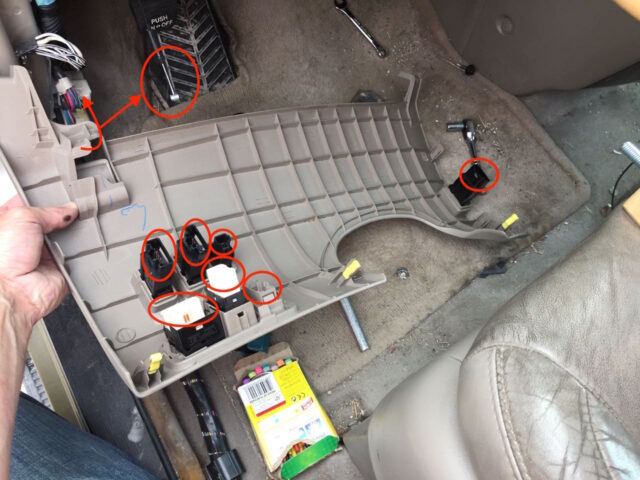
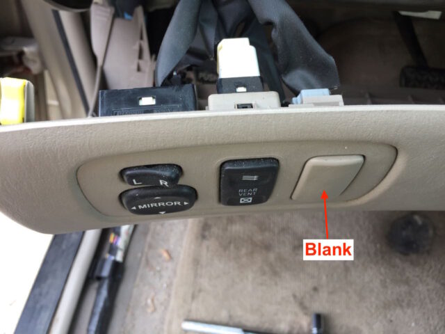
One thing I’ll note is that all the connectors are a different shape so there’s really no worry about mixing them up. The top right connector on the left side, on my van, actually connects to a blank button. I think it is for the side view mirror defrost option, which our van doesn’t have:
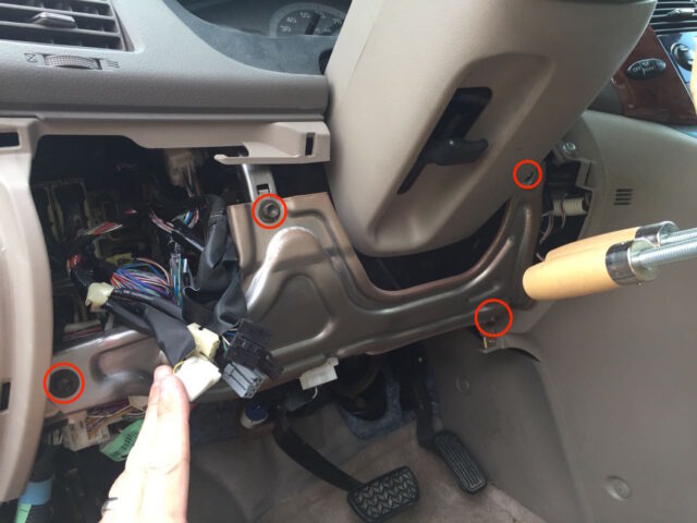
Step 7d: Remove the lower dash metal frame panel.
There are four 10-mm headed bolts located as indicated below.
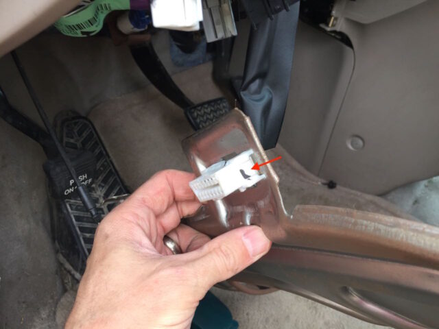
Caution: there is one electrical connector snapped into the metal frame, which must be snapped free before the panel can be removed.
Depress the tab on each side to push the electrical connector out the back side of the panel:
Step 8: Scratch in an alignment mark on the steering column and intermediate shaft.
I’d highly recommend this step as it will aid you in knowing where you are at when you go to reassemble your van. With the lower dash panels remove you can very easily see the entire shaft and have much easier access to mark the top location of the shaft. The top mark was obstructed by the glare of the flash but it is there. I suggest making your mark in line with the center of the u-joint as seen below:
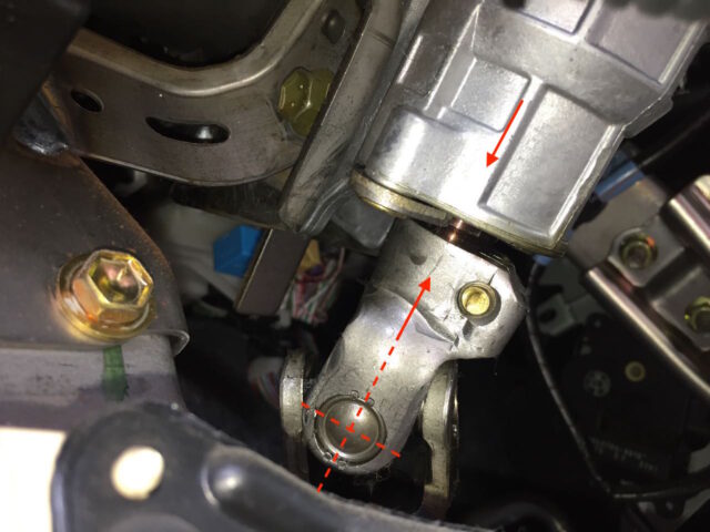
Later you will transfer the mark you made on the shaft side to the new part.
Step 9: Remove the upper end of the steering intermediate shaft.
Step 9a: Remove the upper 12-mm bolt.
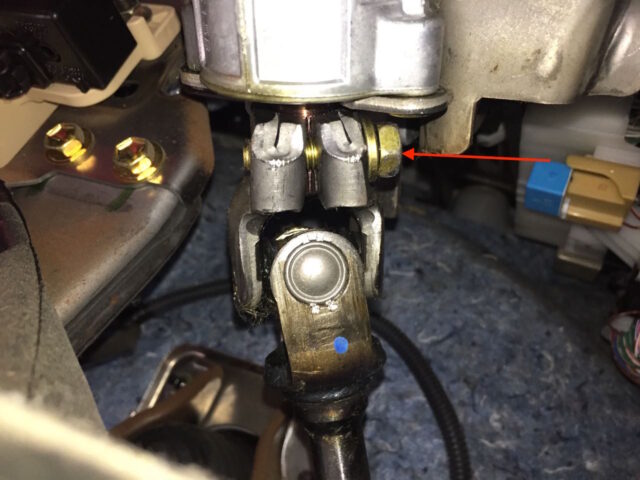
Step 9b: Pry the upper fitting down off the shaft.
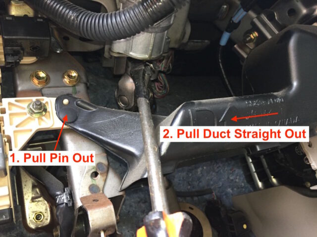
To give myself even more room I removed the ductwork which is in the way by pulling out the black pin on the left and then sliding the ductwork straight to the left and off:
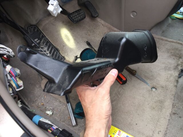
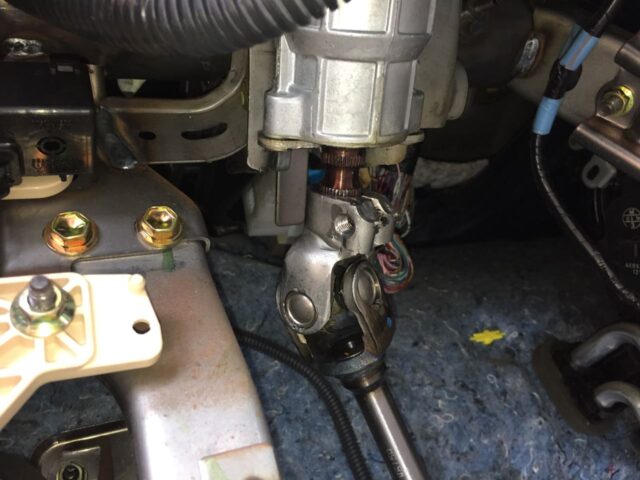
Here you can see the shaft coming down and off:
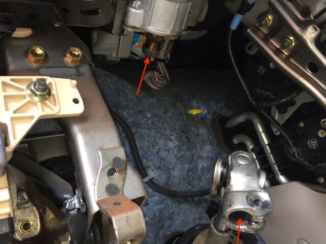
And here the shaft has been removed:
Step 10: Remove the dust boot snap ring.
Pull the tabs of the snap ring out and lift off the dust boot ring:

You can lift up the rubber boot, which is inside the plastic dust cover and the shaft will fall free (if you removed the three 10-mm bolts in Step 5):
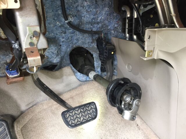
Step 11: Remove the lower end of the steering intermediate shaft.
Laying on your back under the van you can look up and see where the steering intermediate shaft connects to the steering rack. I was able to reach up in a couple different places and at different times each route helped me in a different way. Below you can see how I drove the shaft off, using a screwdriver wedged into the slot of the shaft:
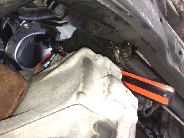
Here’s a magnified view of the the screwdriver tip:
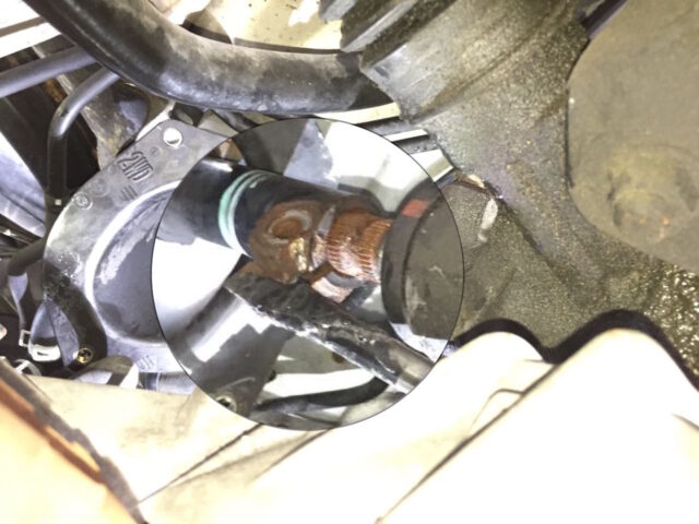
Because my screwdriver is wedge shaped it spread the end while pushing it off the shaft, a great combination. My screwdriver was 13.25″ long, fyi. If you don’t have a screwdriver that long, consider buying one of the long pry bars I have linked up in the tool list. Carefully tap it with a hammer until the shaft comes off.
Step 12: Remove the shaft out through the floor of the cabin.
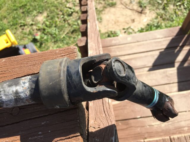
Pull the shaft out from inside the van. Here’s a picture of the shaft removed. The plastic dust boot fell down on the other side of the firewall.
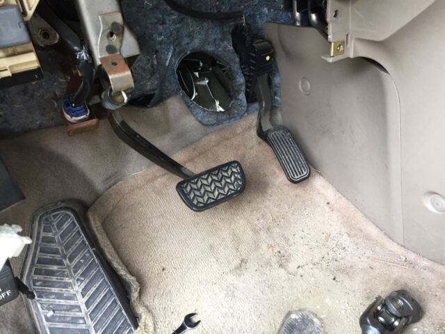
Here’s the guilty party, the corroded steering u-joint:
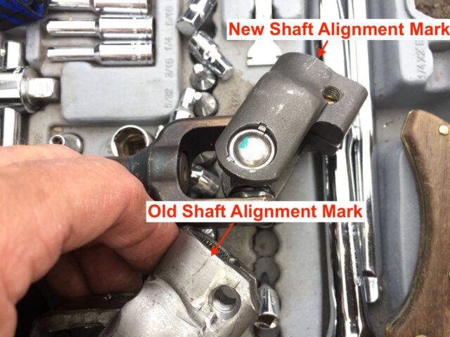
Step 13: Transfer the alignment mark from the old steering shaft to the new one.
I laid them side-by-side and then scratched in a mark to match the old shaft. If you followed my suggestion of making the mark centered on the u-joint pin, you can go by that as well.
Step 14: Insert the new part through the firewall from the cabin side and connect it to the steering column.
Important: Do not forget to slip the metal snap ring onto the top end of the new shaft before you proceed. I forgot when I did it the first time 🙂
Because I re-used the bolts from my original shaft I installed the exterior one on the cabin side and the new one on the outside, as you can see below.
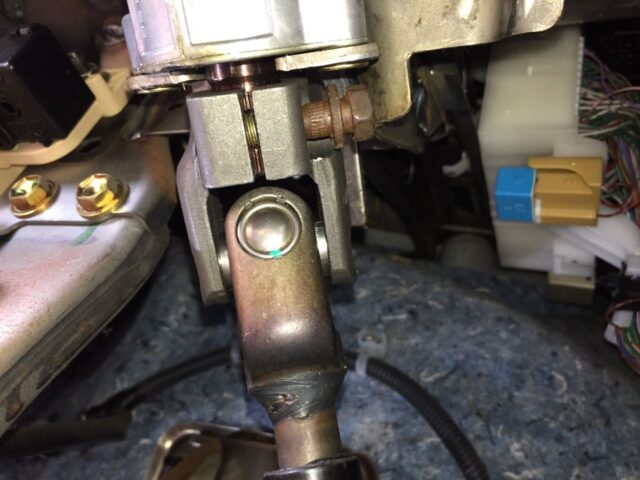
Make sure you insert the shaft with the marks aligned. I’ve highlighted the marks I placed on the two sides with arrows in the image below. Note that the shaft doesn’t slide up flush with the top part. You only need to alight the notch in the shaft with the hole for the bolt.
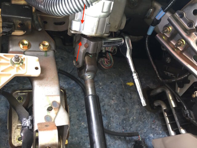
I didn’t torque the bolts but just tightened them good and hand tight.
Step 15: Keep the steering wheel straight.
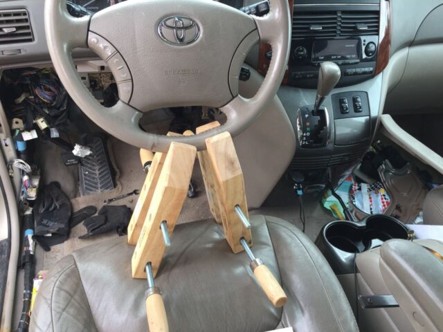
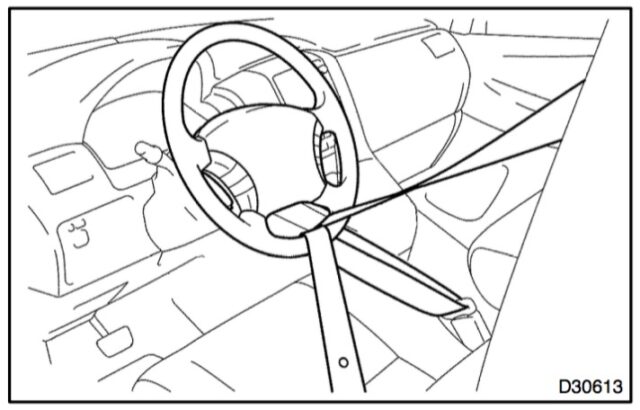
I attempted to use the setup above but ended up having my wife hold the steering wheel centered while turning it back and forth, ever so slightly, so I could get the bottom end of the shaft to slide down on. The shop manual suggests using the seat belt, but I didn’t try that:
Step 16: Install the lower shaft connection.
After attempting to do this by myself, with the clamps holding the steering wheel steady, I decided to have my wife help. The difficulty with this step is that the geared teeth on the male and female connections must line up for the shaft to slide on. I put a piece of masking tape on the steering column with a corresponding one on the top of the steering wheel and marked a line, which marked perfectly straight, and had my wife slightly wiggle the steering wheel around, centered on my two lines. I was able to get the shaft to slide on and I inserted and tightened the lower bolt. The bolt will not go in if the shaft is not all the way on.
Step 17: Verify that your steering wheel is straight.
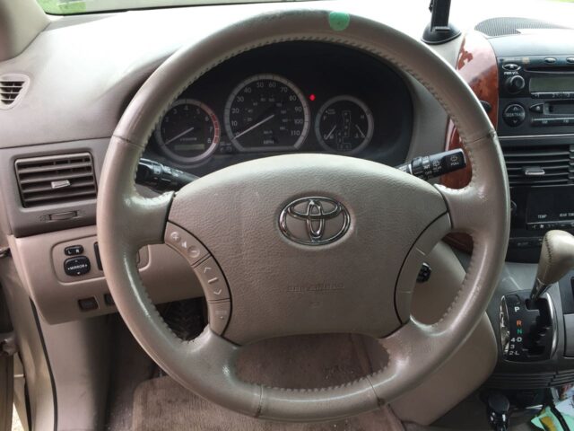
I think there is about 10-degrees per tooth on the steering intermediate shaft (36 or so teeth). If the steering wheel is off by more then 7-8 degrees, you ought to take out the lower bolt, pull the shaft up off, and then re-align the steering wheel and reinstall the lower end of the shaft. I had to do this more than once to get it right and I found that it still seemed like it was something like 2 degrees off, but good enough.
Step 18: Reinstall the dust cover bolts.
I waited until I had the shaft back on to reinstall this so I had the most movement available to get the shaft aligned. Here they are reinstalled:
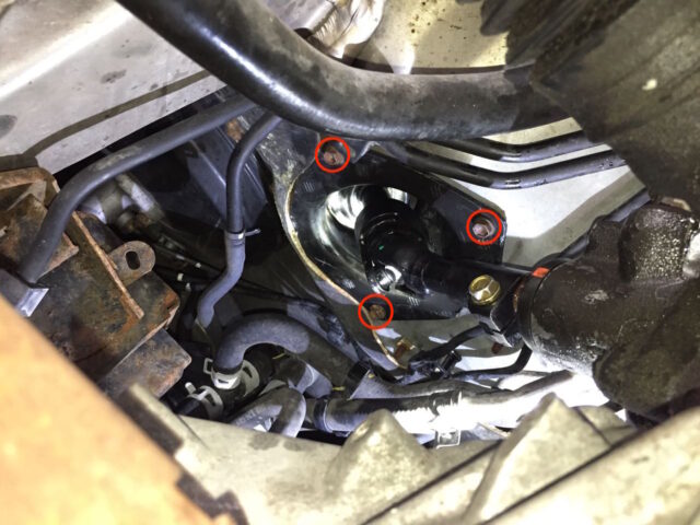
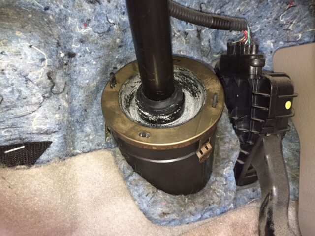
Step 19: Reinstall the top dust boot gasket and lock ring.
Line up the holes in the rubber boot with the holes in the metal snap ring:
Step 20: Reinstall the lower dash components.
If you removed the lower dash components then you’ll need to reassemble the dash. I’ll go through them all and you can skip over if you didn’t take them apart.
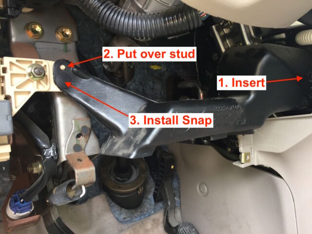
Step 20a: Reinstall the ductwork piece.
Seat the duct back on the opening and then line it up on the stud that sticks out on the left and reinsert the snap:
Step 20b: Reinstall the the lower metal dash plate:
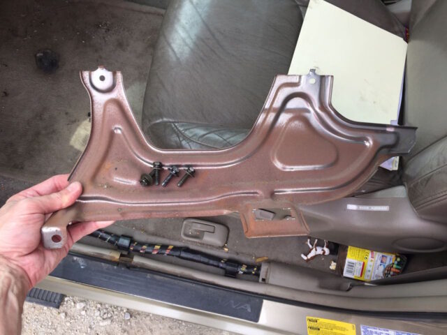
Make sure to snap in the electrical connector first:
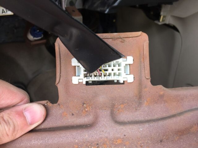
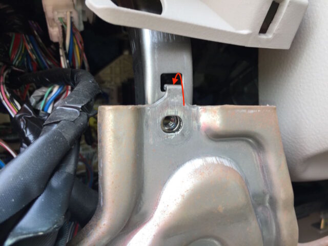
Then hook the metal tabs on each side over the hole in the dash:
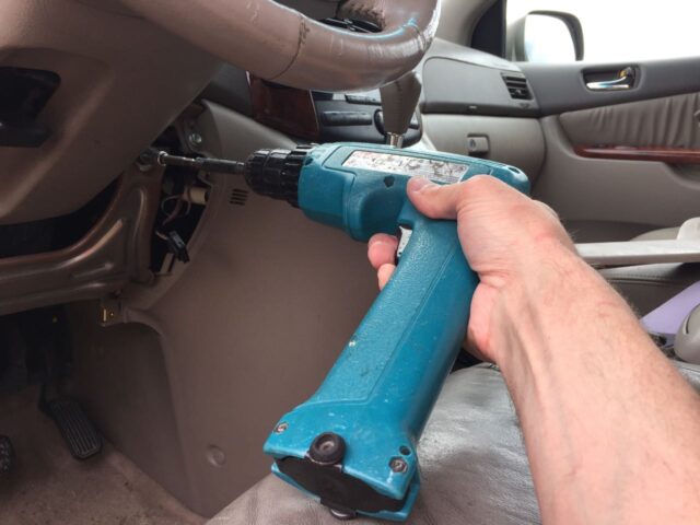
Install the two 10-mm bolts. I have an adapter for my cordless drill that makes this easy. Make sure you start the bolts by hand so you don’t cross-thread them.
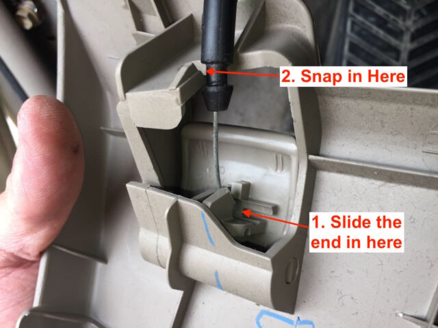
Step 20c: Reconnect the hood latch cable to the lower dash panel.
Step 20d: Reconnect the 7 electrical connectors to the lower dash panel.
Here’s a picture from before I disconnected them. There is one connector in the blank spot on our van. I think that would be for the side mirror defrost:
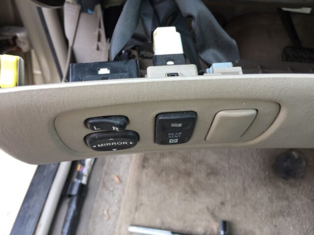
Here are all 6 connectors connected:

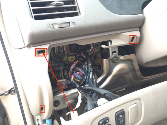
Step 20e: Snap the dash back into place and install the two bolts in the lower corners.
Guide the wiring back into its opening and align the rectangular plastic lugs into their holes where they snap into place:
Step 20f: Reinstall the lower front door trim piece.
Replace the clips onto the trim piece if necessary:

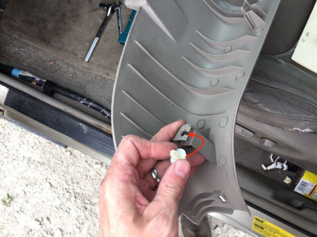
Then snap the piece back into place and install the plastic nut back behind the parking brake:

Step 21: Reconnect your battery.
When you reconnect your battery the traction control system will reset itself. One thing I’ll note is that the driver’s side window will need to be manually powered all the way down and all the way back up again before it will automatically roll itself down or up, so it can learn the extents of the window. Use a 10mm deep socket or wrench to tighten the nut on the battery cable:

Step 22: Share Your Repair!
Now you are finished! No more stiff steering and no more rattle sound traveling up through the steering column. Were you successful in this repair? Do you have tips or corrections to this tutorial? Please leave them in the comments.
Amazon Associate Disclosure: As an Amazon Associate I earn from qualifying purchases. This means if you click on an affiliate link and purchase the item, I will receive an affiliate commission. The price of the item is the same whether it is an affiliate link or not. Regardless, I only recommend products or services I believe will add value to Share Your Repair readers. By using the affiliate links, you are helping support Share Your Repair, and I genuinely appreciate your support.

Very detailed instruction. Cannot expect more. Thanks a lot John!
Very well spelled out for the steering U joint.
Do you have a method for replacing the lift gate cylinders and have them operate by electrical power like the original ones ?
http://www.shareyourrepair.com/2013/02/how-to-replace-rear-liftgate-shocks-on.html
My 02 Camry also suffered from stiff steering and before watching your video I thought the problem was related to the rack and pinion assembly. But it wasn’t.
This repair is too complicated for me. However the penetrating oil, as shown in your other video, worked for me. Thanks for sharing.
Thanks for sharing Hamilton, glad you were able to find a solution that worked for you.