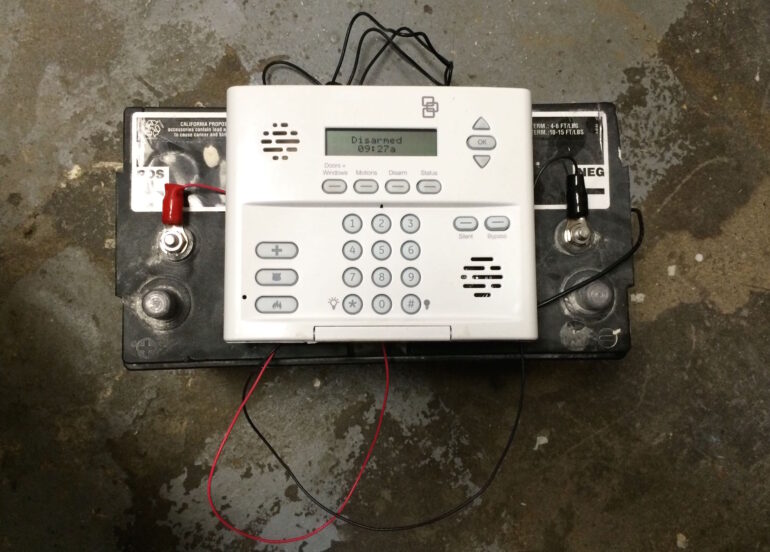
The organization I work for has built over 75 new homes in some of the most economically impoverished neighborhoods in Chicago. Security is a big issue. After becoming aware of the losses we were sustaining I developed a battery-powered solution for wirelessly securing vacant homes that do not yet have AC power.
How to Power Simon XT Alarm With Battery
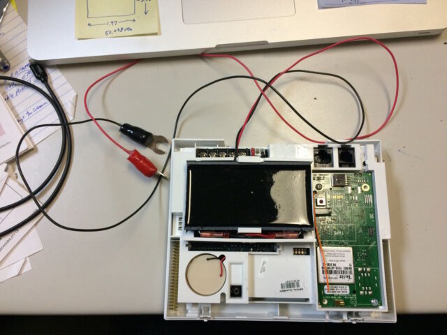
Hardware Required:
- GE Simon XT Wireless Security System 80-649-3N-XT
- Custom Made Simon XT Voltage Regulator (Contact me for more information)
- Large 12-Volt Marine Battery (get a marine battery because it has threaded terminals to easily attach the regulator)
Tools Required
- Phillips Screwdriver (to disconnect the ac power wires from the panel)
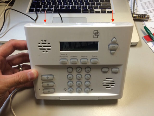
Step 1: Open up the Simon XT Alarm Panel
There are two oval buttons that must be depressed to release the catches on the top of the door of the alarm panel:
Step 2: Remove the internal battery if it is installed.
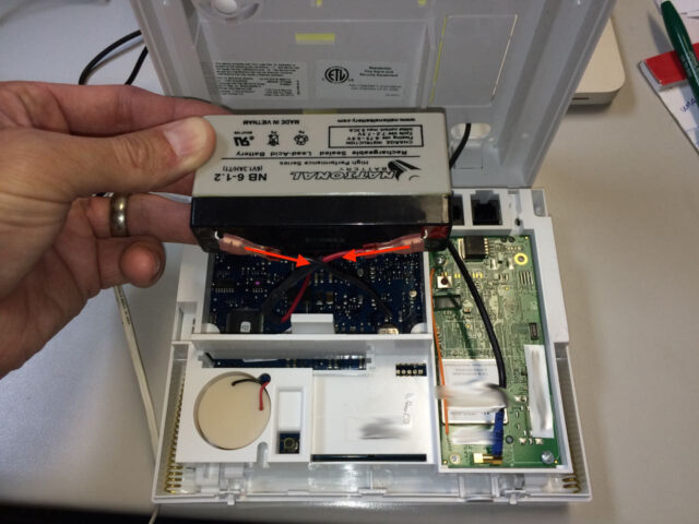
You are going to swap out the battery for my custom-made voltage regulator system that has been designed to be the same size and has the same connectors as the battery it replaces. Spread the two white tabs that hold the battery inside the panel and lift the battery up and out of the alarm.
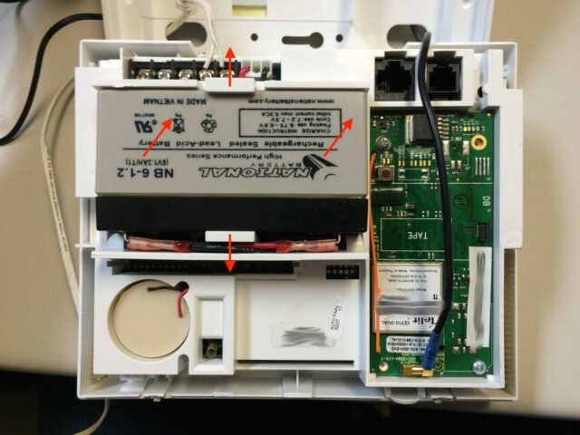
Once the battery is out you can disconnect the positive and negative wires from the battery’s terminals.
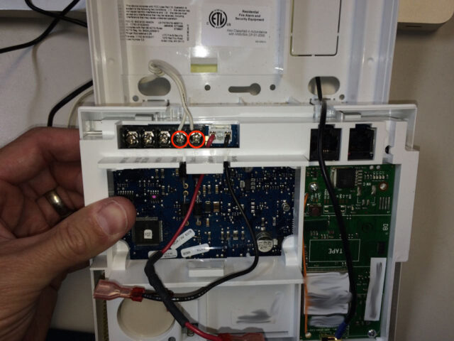
Step 3: Disconnect the AC power cord from the alarm panel
If you plug the alarm into AC power while my voltage regulator is installed, the alarm panel will attempt to “charge” the regulator like it is the battery and this could damage the regulator. It’s best to disconnect the AC power cord when you are operating it in battery-powered mode. Loosen the two Phillips head screws that hold the AC power wires:
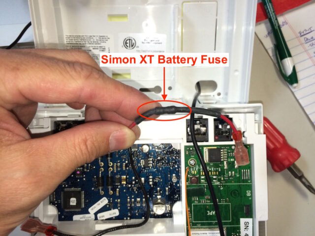
Step 4: A word of caution about wiring polarity.
There is a built-in fuse in the battery wiring. If you connect the battery or the voltage regulator it will blow the fuse. The fuse is not user-replaceable so you’ll need to buy a new wiring harness. Be careful when connecting the wiring. Red wires stand for positive, or +, and Black wires signify negative, or -.
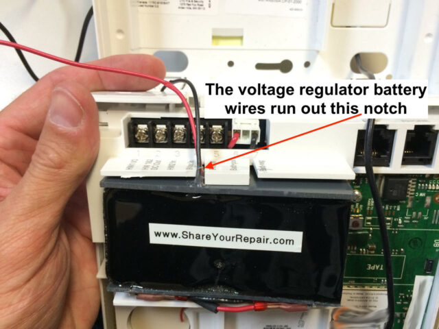
Step 5: Connect the voltage regulator to the alarm wiring.
Connect the red alarm battery wire to the + on the voltage regulator and the black alarm battery wire to the – on the voltage regulator as seen below:
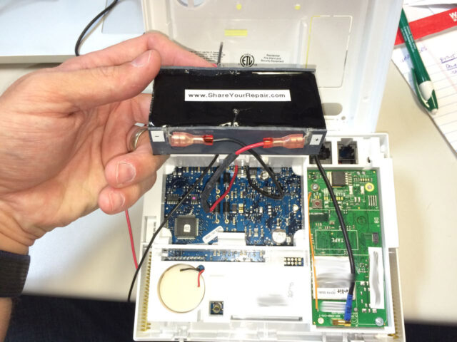
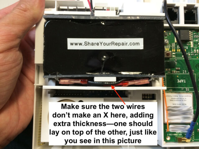
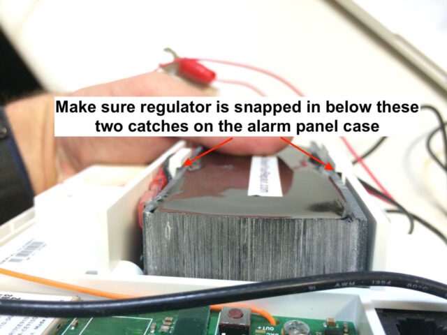
Step 6: Snap the voltage regulator into the alarm panel.
The voltage regulator is designed to fit into the alarm just like the battery it replaces. Make sure the battery wires don’t make an X where they cross each other or it will make the wires too thick and it will bend the case. Also make sure the voltage regulator is below the lips on the two plastic arms that held the battery in place.
Step 7: Run the battery wires out the holes in the alarm panel
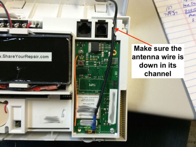
Now I must admit that my battery spade connectors are a bit big and they are a tight fit to feed out the holes in the alarm panel case. They will fit out though, one at a time:

Step 8: Close up the alarm panel.
It should snap tight. If it does not, you may not have the voltage regulator snapped into the battery slot correctly. Often, if the alarm doesn’t want to shut it is because some of the wires are getting in the way when you are closing it–gently pull the wires leading out of the bottom of the alarm panel to pull out any extra wiring that may be getting in the way inside.
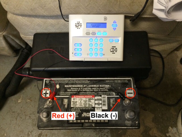
Step 9: Connect the voltage regulator to a 12-volt battery.
I buy the biggest 12-volt marine battery I can buy so it will last as long as possible. Connect the red connector to the positive (+) of the battery and the black connector to the negative (-) of the battery as seen below:
Step 10: Run a Communication Test
If you have a wireless modem inside your Simon XT then the first thing you should do after powering it up is to run a communications test to establish communications between the alarm provider and the alarm panel. To run a communications test follow these steps:
Step A: Press the down arrow button until the screen reads “System Tests” and then press the OK button.
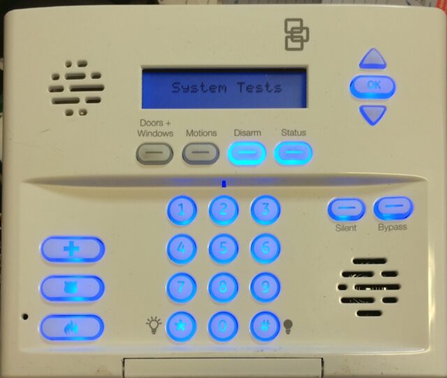
Step B: Enter the programmers code and then push the OK button.
You’ll need to have been given this by whoever you purchased your alarm from.
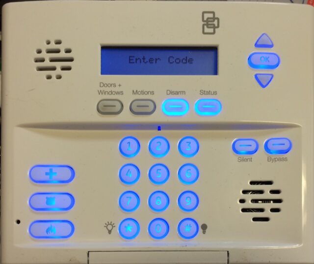
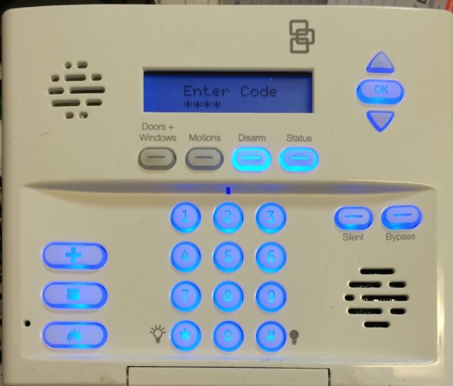
Step C: Press the down arrow until the screen reads “Comm Test” and press the OK button.
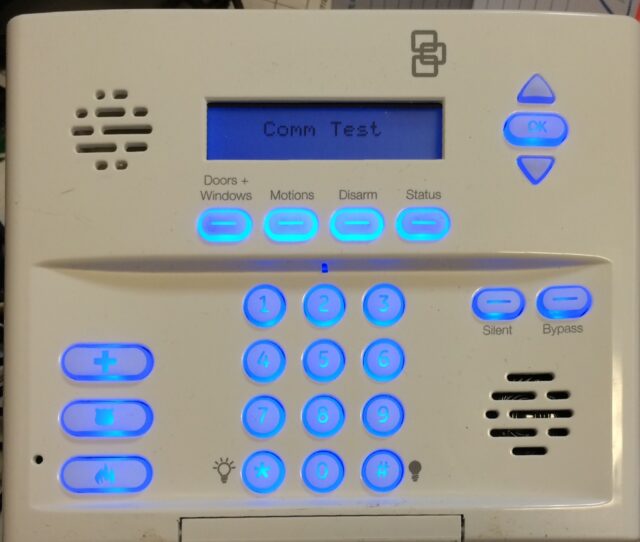
Step D: Wait for the test to run.
This is what you will see while it is running:
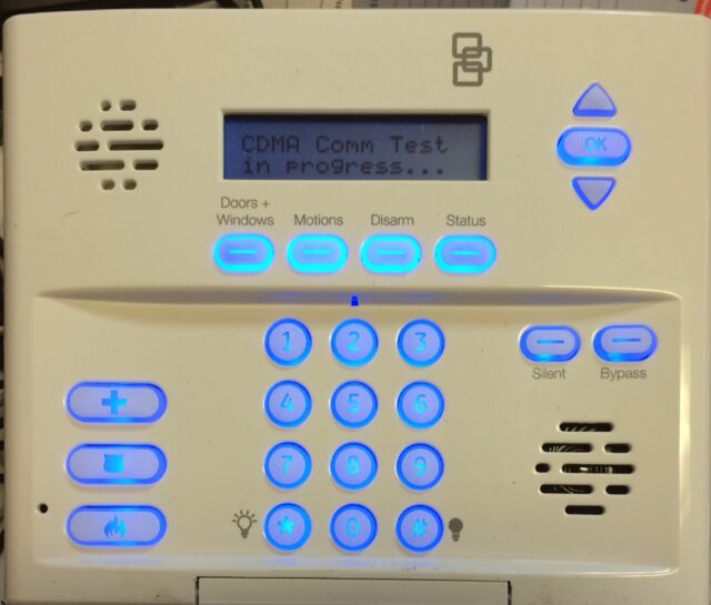
It should say “CDMA Test signal sent OK” or “GSM Test signal sent OK” if it is successful. Press Status now” if it runs successfully. If it doesn’t run successfully your antenna may be disconnected or you may be located where there is weak signal.

Step 11: You can check the signal strength by pressing and holding the 5 button from the main screen:
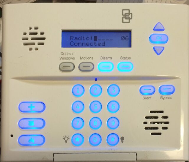
I cannot remember the range of numbers it can give you but you can see the “bars” and there are 5 possible and in the case above, I only have 1 bar of strength. I believe the number range is 0-20.
Step 12: Check the voltage being provided to the alarm by the voltage regulator.
The Simon XT alarm panel has a digital multimeter built into it and you can check the voltage of the internal battery OR in our case, the output of the voltage regulator. When the Simon XT is at the main screen press and hold the 6 button as seen below:
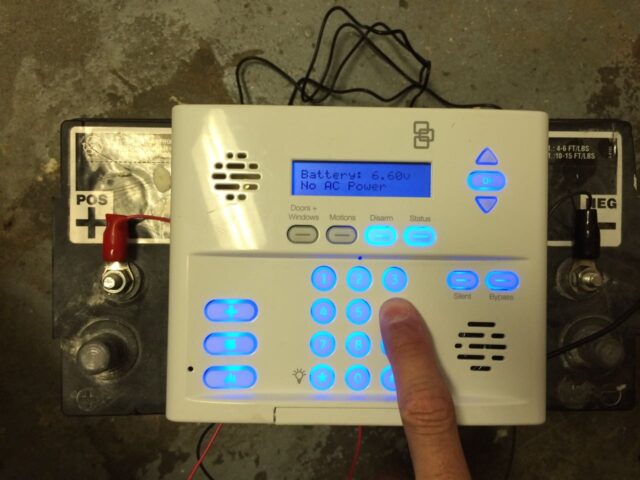
Here’s what our application looks like with the Simon XT alarm panel mounted on a small custom-made base that allows for easy portability:

Amazon Associate Disclosure: As an Amazon Associate I earn from qualifying purchases. This means if you click on an affiliate link and purchase the item, I will receive an affiliate commission. The price of the item is the same whether it is an affiliate link or not. Regardless, I only recommend products or services I believe will add value to Share Your Repair readers. By using the affiliate links, you are helping support Share Your Repair, and I genuinely appreciate your support.

