I have really become interested in LEDs since they have improved a lot and their price has come down so much and I like to find ways of saving money. I had seen 100W LEDs available and wanted to buy one and try it out for myself. I finally got around to it and here is how to power a 100W LED…
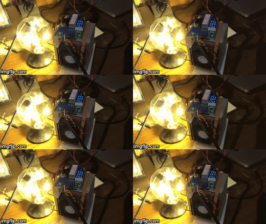
How to Power a 100W LED
Parts Needed:
- 100W LED
- 3.5V-30V DC Boost Converter Power Transformer Voltage Regulator
- 12V 3A Power Supply
(I used the power supply from bad 2Wire wireless access point I had saved)
- Heatsink (get both the heatsink and fan here: CPU Heatsink and Fan Combo
)
- 12V Computer Case Fan
(I just used one I’d scavenged from an old PC–it is crucial that you have a fan on the heatsink–read my Lessons Learned section at the bottom to find out why!)
- Heatsync Thermal Paste
- Focusing Lens (optional)
Tools Needed:
- Wire Stripper
- Precision Screwdriver Set
(to adjust pots on regulator) - Voltmeter (I really like my Fluke 177 True RMS Multimeter
)
Alternative Things I Use:
- Radiometer
(it was fun to have this thing spinning on the power of the LED light–movement makes things look cooler!)
Step 1: Collect all the components.
I ordered my 100W LED and the DC-DC Boost Converter Power Transformer off of Amazon using the links I share above but all the other parts I had laying around my workshop. I always save old power supply cords for such a time as this and I had a 12V 2.9A DC power supply that has 2Wire written on it so it must have been from someone’s DSL modem. I had a big CPU heatsink I had saved from disassembling an old computer, and I used a small 12V fan from a computer I had torn apart some time ago too. I also had the thermal paste left over from an x-box repair I did a long time ago. Try to reuse what you can!
Step 2: A Cautionary note about handling a 100W LED.
Do not press on the yellow substrate area–you can destroy the LED. Also, once we get it turned on, it is going to get hot, so don’t burn yourself and touch the LED surface!
Step 3: Determine the polarity of the LED connections.
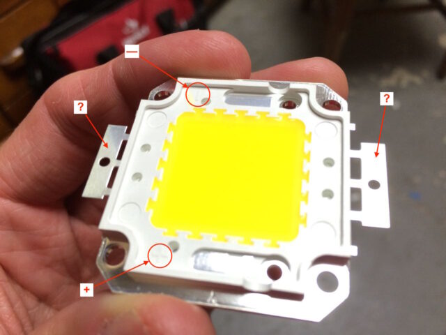
The LED has a + and – marking on the top left and bottom right but they don’t help you know which of the two metal tabs on the right and left to connect to though AND the documentation given on Amazon seems to be backwards to me. On the physical LED there is a positive and negative symbol, but they give you NO CLUE as to which of the two tabs which goes to:
So I decided to do some checking with my Fluke 177 Multimeter to see what connects to what. With the multimeter in the diode testing setting, which plays a sound when a short circuit is found, I started checking to see which tab was connected to which side (top or bottom). What I found was that, when oriented as seen in the pictures above and below, the right tab is connected to the exposed metal plate on the bottom, by the + symbol, so the right tab must be the positive:
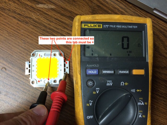
I went ahead and checked the other tab and it was consistent, and the top exposed plate and the left tab are shorted together, so the left tab must be the negative terminal.

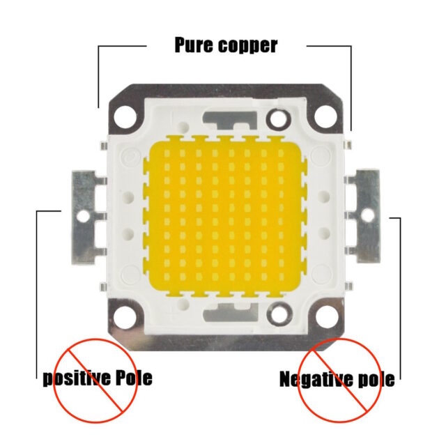
This is BACKWARDS from what they tell you on Amazon, so beware:
Step 4: Attach the 100W LED to the heatsink.
This LED cannot be run without a heatsink of some type! Don’t ruin yours by powering it up without one.
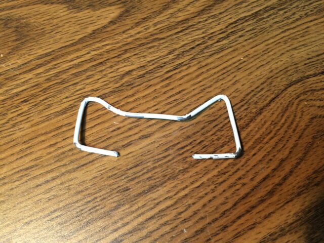
There are four screw holes in the LED, made for mounting it tight but my heatsink didn’t have corresponding holes and I didn’t want to drill holes in it at this point since I’m just messing around. I’ve seen heat sinks held into place by metal springs and I thought I could hold the LED down on the heatsink with some heavy wire, actually a coat hanger I had laying around that I had used earlier to dig hair out of one of our sink drains. I bent two M-shaped pieces, except the bottom legs of the M’s bent in to hook onto the heatsink. This is what they looked like:
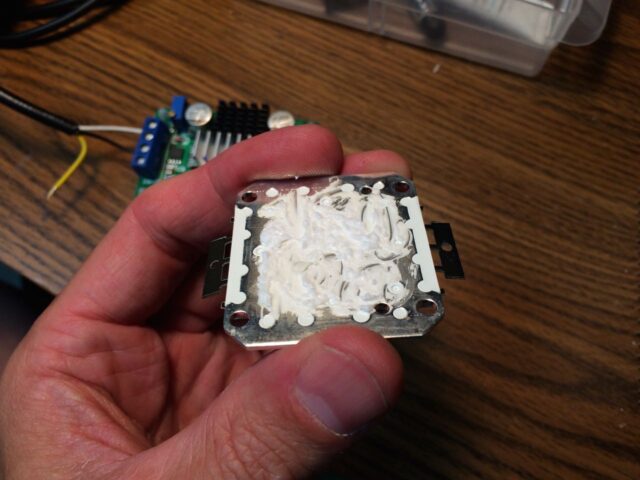
I then put thermal compound on the back of the LED. Thermal compound is critical to make a good thermal connection between the LED and the heatsink. If you don’t put it on there will actually be an air gap between the two because the surfaces are not perfectly smooth and air doesn’t conduct heat like thermal paste or aluminum does. Without thermal compound the heatsink will not pull the heat away from the LED effectively.
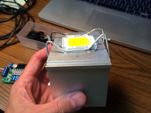
Then I took my wire brackets and clamped the LED to the heatsink. I shaped the wires to they are pressing down on the heatsink, so it makes a good thermal connection.
Step 5: Familiarize yourself with the Step-Up Voltage Regulator

Step 6: Connect the LED, cooling fan, and power to the Step-Up Regulator
Solder a wire to the now-known positive and negative terminals of the LED. I’d encourage you to color code it so you can easily tell which is which. I used the typical red for positive and black for negative. What we are going to do, since the cooling fan is 12 Volts and the power supply I’m using to power the Step-Up regulator is 12 Volts as well, I’m going to connect the fan to the same input connections on the Voltage regulator. The input and output connectors are a little weird on this regulator in that there are pairs of negative inputs and pairs of positive inputs and the same goes for the output. It works good for powering the fan, because we can connect the fan to one set of inputs and connect the power supply to the other set:
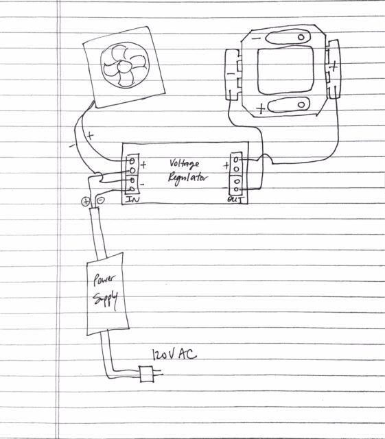
I cut the end off the 2Wire power supply and there were three wires: yellow, white, and black. I used my multimeter to determine which wire was which. It turns out the yellow was 12 volts, the black negative (of course), and there was no voltage on the yellow–it must be some kind of feedback wire, who knows.
And here’s what it looks like in real life all wired up and ready to go:
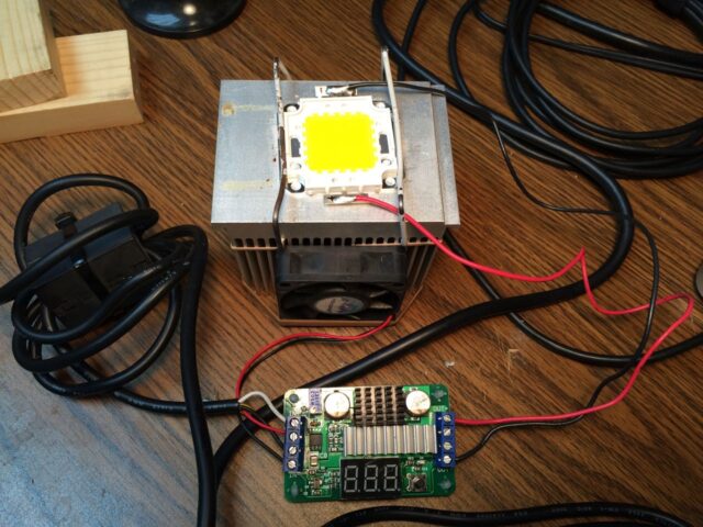
Step 7: Power it up.
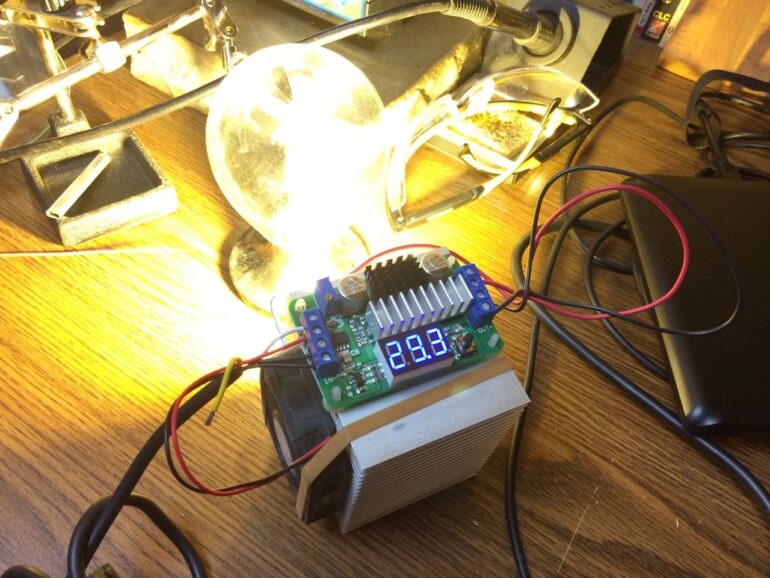
I have to confess that when I first powered it up, nothing happened. The problem was that the output of the step-up regulator was set too low for the LED to come on. I found that the voltage must be at least 21 volts before any faint appearance of light shows up on the LED:
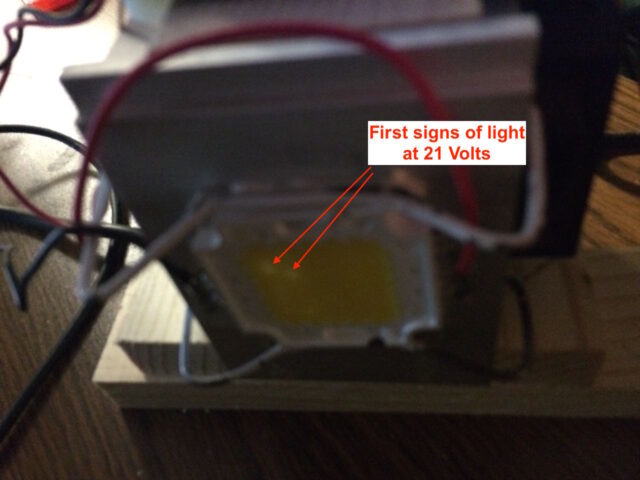
At 25 volts it begins to get bright:
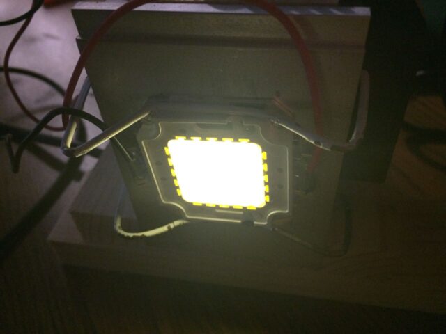
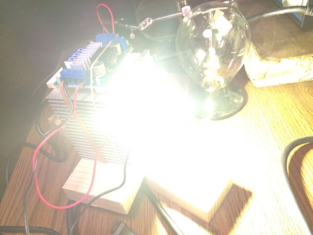
At 30 Volts, it is BLINDING:
Step 8: LED Power analysis.
Just out of curiosity I wanted to know how much current the system was using. The heatsink wasn’t even getting warm so it didn’t seem to me like we really had this LED running at 100 watts. Just FYI, power is calculated by current times voltage: P = I x V.
The Power supply was pulling 2.1 amps at 12 volts, 25.2W. I tested it by moving the lead on my multimeter to the 10A connector and putting it in series with one of the wires coming from the power supply. By “in series” I mean I disconnected the negative leg of the power supply from the regulator and hooked up one multimeter probe up to the negative connection of the voltage regulator input and the other one to the negative on the power supply (which I just disconnected) so the current is passing through the multimeter):
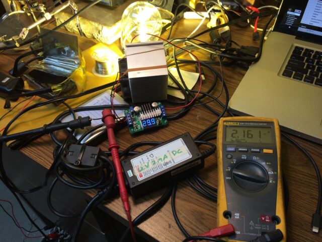
With the multimeter in series with the positive connection to the LED I found out that the LED is only pulling 700 mA:

What’s happening is that this step-up converter is not capable of supplying the full 100W of power needed by this LED. The heat sink doesn’t even get warm at only .686 A x 30 V = 20.58 Watts. I figured out that the power supply was using 25.2 W total, so knowing what we know now we can calculate the actual power being used by the DC Step-Up Regulator: 25.2-20.58=4.62W. And you can feel the heatsinks on the regulator get warm (where some of the power is going–heat). Oops, I forgot one thing–the fan. This isn’t taking into consideration the fan’s power usage. I put my multimeter in series with one of the fan’s leads and found out it is pulling about 30 mA, or .03 Amps of current. This means the fan consumes 360 mW of power, not that much, but some, from the 12V power supply we have, that only is capable of 25.2W.
We need a power supply that is capable of more amps. This makes sense because the power supply I was powering this system with is rated at 12 volts at 2.9 Amps, this is only 12*2.9=34.8 Watts. You can’t get 100 watts out of a system when you are only putting in 34.8 Watts and the step-up converter is getting hot, i.e. wasting 4.62W of power in the step-up process.
Lessons Learned
A Fan is CRITICAL on the heatsink (if you use one similar to the one I used)
I kept feeling the heatsink and it hardly gets warm at all so I began to think that the fan may be unnecessary. To test out my theory I disconnected one of the leads on my fan and let it go fanless. I should have watched it closer because I forgot about it and went about my business and when I went to check and feel the heatsink, it was SUPER HOT to the touch. I quickly turned on the fan and got it cool again. I cannot see that I damaged the LED but that would not be good to let it go for long.
Amazon Associate Disclosure: As an Amazon Associate I earn from qualifying purchases. This means if you click on an affiliate link and purchase the item, I will receive an affiliate commission. The price of the item is the same whether it is an affiliate link or not. Regardless, I only recommend products or services I believe will add value to Share Your Repair readers. By using the affiliate links, you are helping support Share Your Repair, and I genuinely appreciate your support.


I may just keep it at a single setting actually. Do you have any suggestions for a lens cover of some sort to keep it from getting dirty?
They sell a lens for that LED, which you can get here. I have added a link for this in the parts section of the article as an optional part.
Great post! I’m planning on 3D printing a case to enclose all of the wiring and voltage regulator. Do you have any idea on how to adjust the potentiometer set screw easily? Like putting a knob on it?
Thanks for the feedback Andrew. The pots on that regulator aren’t made for knobs to be added to them although anything is possible with a little determination. There’s multiple routes you could go… trying to connect a knob to the existing pot or desoldering these pots and installing an equivalent one which is made to have a knob on it. Let us all know what you do if you move forward with your project.
Do you have an offline email for me to bounce ideas off of you?
I will do it. I would like to narrow the beam from a flood to a spot. Any thoughts, like some type of Fresnel lens?
They sell a lens specifically made for that exact LED (but a Fresnel lens is not necessary and they are much more expensive). Here’s a lens for the LED I have linked above:
44mm Lens + 50mm Reflector Collimator Base Housing + Fixed bracket for 100W LED Light Lamp
You are awesome, thank you so much. After I build it, I will send you some images. Will be a couple months though.
Glad to be able to help. If you take pictures of all the steps, take notes of what worked, what didn’t, and how you were able to work around the issues then we could add an article to showcase what you built. That’s why I named this site Share Your Repair! If you do, please let me know: Contact Me
Thank you for the quick response and yes it does answer the portion on the power source from the vehicle.
I would like to confirm the step-up converter you suggested is capable of reaching 100 watts as well.
Thanks again Kevin. I went to the product page of the DC Step-up converter I have linked on this page and below is what they have as the specifications. They say that the max continuous current is 6 amps. If you are supplying 30 volts with the equation P=IV, or I=P/V, and assuming 100 watts, I=100/30=3.3 amps. So, theoretically you could do it but it is at the maximum power output of this converter. I picked it because it was cheap and easily available. If you want to pick something that could steadily and easily put out 100 watts for the long term, you want a circuit that has a max much higher output capability than 100 watts. Here are some options:
Geeetech 150W Boost Converter DC-DC 10-32V to 12-35V Step Up Voltage Charger Module
DROK® 600W 12A DC Boost Voltage Converter 12-60V to 12-80V Step-up Power Supply Transformer Module
DROK® DC/DC Boost Converter 12-60V to 12-80V Step-up Voltage Regulator 600W Auto Power Supply Transformer
Specifications:
Input voltage: DC 3.5V-30V(please leave margin in usage, or meter will burn)
Output voltage: DC 3.5V-30V(boost module; ensure input voltage < or = output voltage) Continuous current: 6A(long-term work) Max input current: 10A (peak) Output power: 100W Max(U-in * I-in * Efficiency = U-out * I-out) Voltmeter accuracy: +/- (0.5% +1 digit) Static power consumption: typically around 15ma
If I were to get my power supply from a running vehicle (12 volt system) to include the alternator output (13-14 volts) would this give me the power I need to get to 100watts? My purpose for using the vehicle power is a powerful light for roadside repairs.
When you stated “What’s happening is that this step-up converter is not capable of supplying the full 100W of power needed by this LED.” was this because of the power supply or the step-up converter? I think you explained it later (still a little fuzzy to me) in the power supply portion. I just don’t want to buy the wrong step-up. Nice article by the way.
Thanks for the question. Power (measured in watts) equals current (measured in amps) times voltage (measured in volts) or as P=I*V. You can re-arrange the equation however you like with algebra and calculate the current required to supply 100 watts at 12 volts: I=P/V or I=100/12 and therefore I=8.33 amps. Now any car battery will be able to provide 8 amps because a starter for a 6-cylinder gas engine is in the 200 amp range. Albeit, you don’t run your starter for long. So, if your vehicle is running, you should be able to power a 100 watt LED long-term because it only pulls around 8 amps. If you power a 100-watt LED on a battery without the vehicle running (and the alternator recharging the battery) you will drain the battery. You could theoretically calculate how long using the amp-hour rating of the battery. You Does that answer your question?
Hello John ~
Thanx For Sharing This … I’ve been interested as well in putting together something with one of these 100 watt LED’z for quite some time, but i know even much much less about these things than you by far …. so this was very helpful for me …
Quick question for ya;
Being that your unit was only running on 34.8 watts, or was it 24.8 watts? You kinda confused me on that last paragraph … however, if i were to gather materials for this project, would i instead want to acquire a power supply that is rated more like 12volts 8amps? … would a 12volt 10amp power supply burn out the LED or something due to it being over 100 watts?
I’d love to know these things and whatever else you could possibly add to help maximize the potential of my unit … also i was hoping to build it into a mega flashlight of sorts so if i should do anything different because of that, i’d love to know as well ~
Thanx again John >
AlohA^
JeSse BLakTi
Jesse, thanks for the comment. Yes, you are right–that was confusing because I had a typo in that article. Both numbers should be the same, 34.8 watts and I have now corrected the article. Thank you for pointing that out. Yes, the power source you use must be capable of sourcing 100 W in order to get 100 W out of the LED. The power supply must be able to put out the optimum voltage for the LED and the current to make the power be 100 watts where Power = current x voltage. There are many tutorials out there on youtube where people are showing their 100W LED flashlight builds. I haven’t been able to find a good real-life practical application for my LED yet honestly. In regard to a flashlight, you need the battery power to source the power supply and 100 W will burn up a bunch of batteries fast. Thanks for commenting, John.