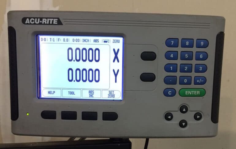
I’m taking a National Institute of Metalworking Skills class and I learned how to use the DRO on our knee mill and I wished I would have known how to use it a long time ago because it works great. I had some hand-written instructions provided by our instructor on how to zero it out but they weren’t quite right so I wanted to write them up for my own personal reference and to share with others. Here’s a step-by-step tutorial on how to zero out Acu-Rite digital readout (DRO):
How to Zero Out Acu-Rite Digital Readout
Hardware:
- Acu-Rite Model DRO 200S 2X M, Part Number: 532 882-12 (discontinued)
- Vectrax CL Series J-Mill, Model 72526049
- Edge Finder Single, 3/8″ Shank x 0.200″ Head Diameter
Step 1: Mount your part in the vice and square it up.
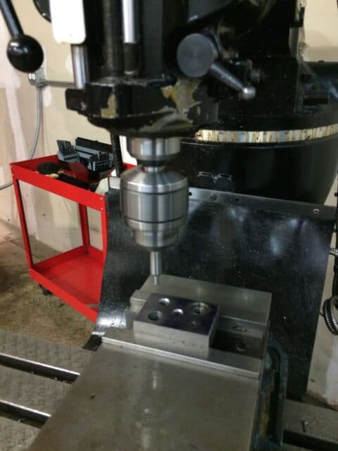 |
| My NIMS drill press project mounted in the vice (For better accuracy put the edge-finder in a collet, not a Jacobs) |
Step 2: Turn on the Acu-Rite and let it boot up.
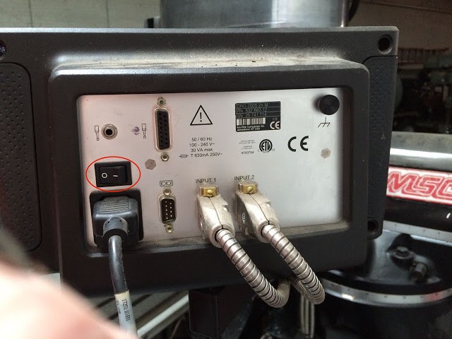 |
| Location of the power switch on the back of the DRO |
This is the screen you’ll see when it’s fully booted:
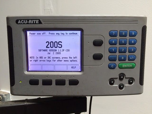 |
| Acu-Rite just booted up – Press any key to continue |
Press any rubber button to get past the boot screen. You could now possibly see a screen that says “No Ref” as seen in the image below:
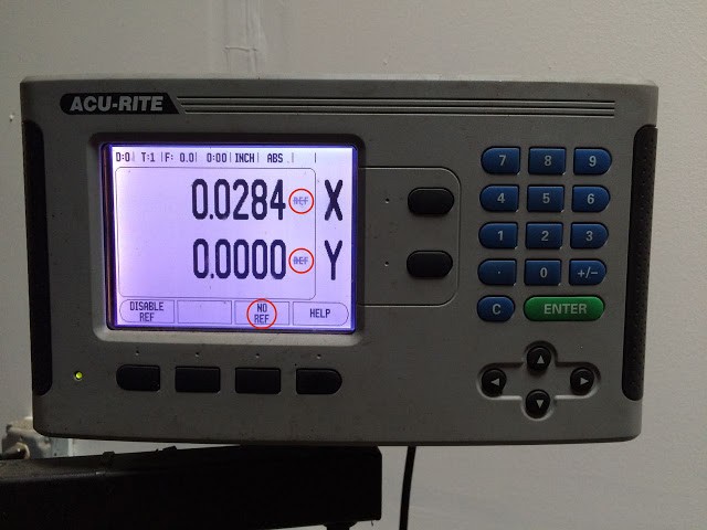
The reason the DRO is indicating “No Ref” is because it doesn’t have any reference as to where the table is at when it came on (you could have moved the table while it was off!!). There is a mark that you can pass that will tell the DRO where it is and you can manually crank the wheels to pass that mark but since we want to zero out the DRO on the location of our part mounted in the vice we should just press the black button below “NO REF” on the screen. You will then see this:
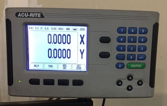 |
| It will read 0,0 wherever the table is once it boots up and you clear the No Ref indication |
Step 3: Put the DRO in ZERO mode so you can zero-out the x and y coordinates.
The button that toggles this mode is the far right black button below the screen. Look in the top right of the screen for “ZERO.” If you don’t see ZERO then press the SET/ZERO button until you do. When you press it you will see it cycle through: SET ZERO ABS in the top right corner of the display. We want it to say ZERO:
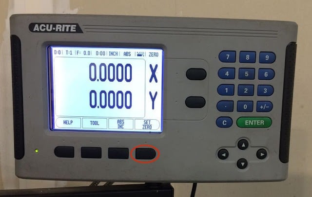 |
| SET ZERO button |
Step 4: Move the edge-finder up to the very edge of your part.
Now you will want to consider the plans and the edge that the plans use to measure the details on the part. If the plans measure everything from the back of the part then you should zero out on the back. If the plans measure from the left size then you should zero out the y-axis on the left side. This may mean that the readout will be negative numbers but that won’t matter. To zero out an axis, mount an edge-finder in a collet in the mill and then turn it on. Tap the end of the edge-finder with your finger to put it out of balance and slowly move in to the edge you want to zero out on. This DRO actually has the x-axis going horizontally and the y-axis vertically. You’ll need to figure out which is which on your DRO. Make sure the “seam” on the edge-finder is above the top of the part, otherwise you’ll just be running the edge-finder into the edge of the part.
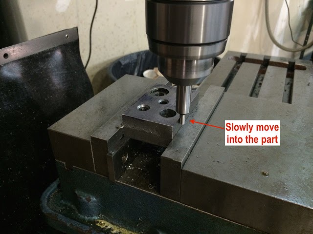 |
| Zeroing out the Y-axis on my DRO |
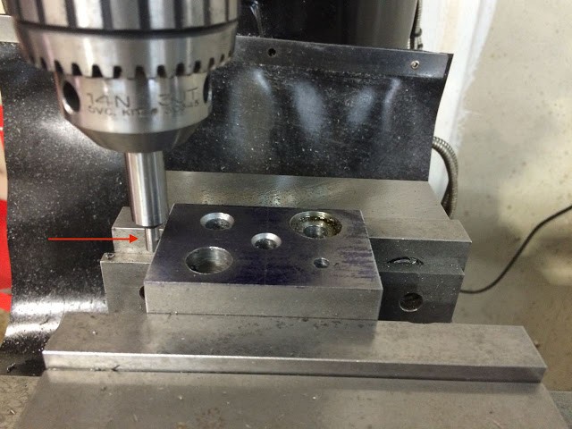 |
| Zeroing out the X-axis on my DRO |
Step 5: Zero out the axis.
The seam on the edge-finder should be perfectly even and not wobbling around. Once you have the edge-finder touching the edge and running smoothly, press the black button to the right of the axis you are zeroing out:
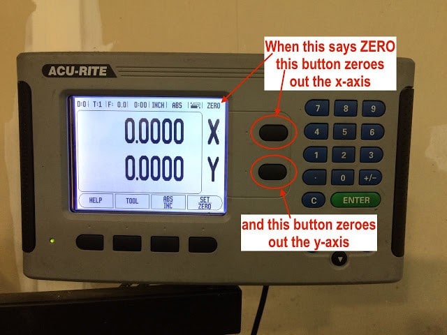 |
| X and Y Axis zero out buttons |
One thing you’ll need to remember is that the center of the tool is still actually half the diameter of the edge-finder away from the part, even when zeroed out:
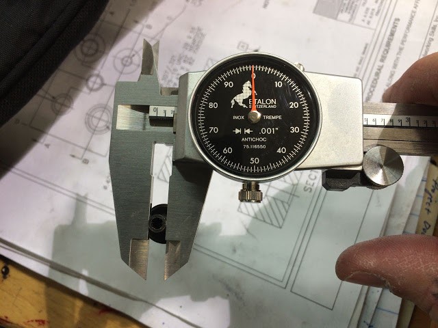 |
| My edge-finder is two tenths in diameter |
Whenever you are moving the mill into place you will need to remember to add .100 to all your measurements to compensate for the thickness of the edge finder. Alternatively, you can lift up the edge-finder and for both the x and y axis’, move it into the piece until the DRO reads .100″ and re-zero out the DRO and then your DRO will have actual measurements. It’s all up to your preference how you want to do it.
Now you can make very precise measurements on your mill! No more eye-balling the centering of those holes!
Other pertinent links:
- Acu-Rite DRO 200S Manual (pdf)
Amazon Associate Disclosure: As an Amazon Associate I earn from qualifying purchases. This means if you click on an affiliate link and purchase the item, I will receive an affiliate commission. The price of the item is the same whether it is an affiliate link or not. Regardless, I only recommend products or services I believe will add value to Share Your Repair readers. By using the affiliate links, you are helping support Share Your Repair, and I genuinely appreciate your support.

