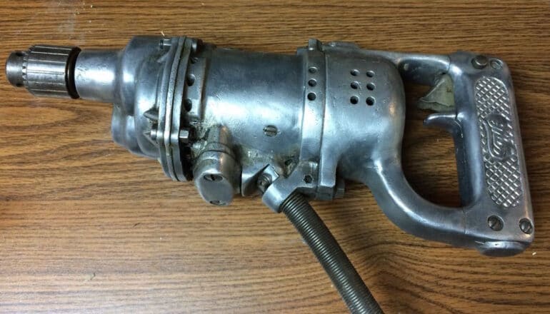
A coworker brought me a vintage Thor Model 4199 drill to see if I could fix it because it would not work. Looking at the cord made me think the problem was likely a short:
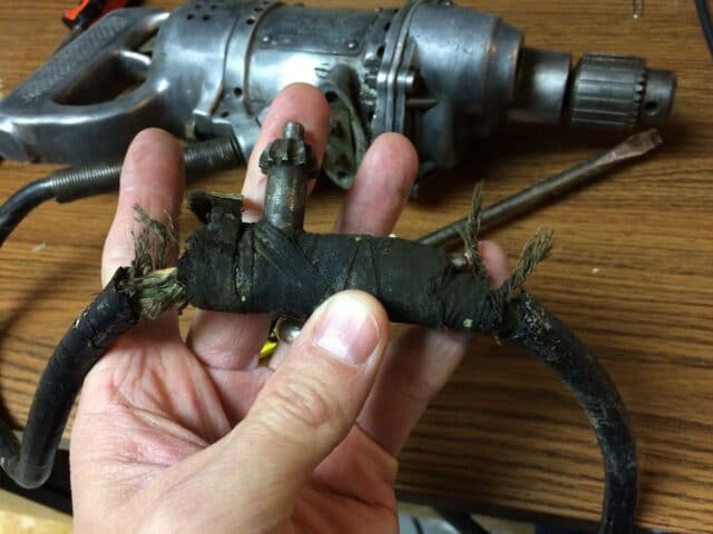 |
| The cord looked like it came out of a scary movie |
Here are the steps I took to troubleshoot and repair this neat old “they don’t make ’em like they used to” drill:
How to Fix the Switch and Change the Cord on a Vintage Thor Model 4199 Drill by Independent Pneumatic Tool Co
Tools Needed:
- Multimeter, I really like my Fluke 177 True RMS Digital Multimeter with Backlight
- A variety of sizes of flat-head screwdrivers
- Soldering Iron, I used a high powered gun type like this one
- Solder
- 1/4″ socket driver (get this and all the other sockets you’ll need with this set here
)
- Precision Electronics Cleaner
Parts Needed:
Step 1: Remove the cord’s access panel.
The drill should be unplugged at this point, I just wanted to mention that. I first wanted to verify that there really was a short in the cord. I hadn’t even tried plugging it in but I wanted to do some testing before I did anything and before I assumed anything. There is a plate with two flat-head screws on it just next to where the cord enters the body of the drill. Remove the two flat head screws:
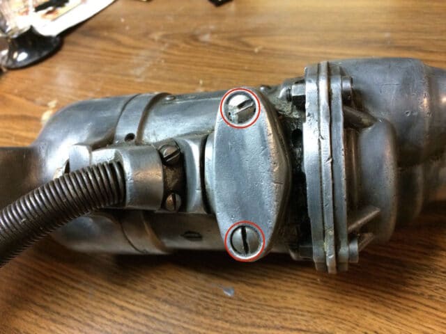 |
| Access panel screw locations for the cord connection to the drill |
After you remove the two screws you may need to pry the cover off, depending the condition of the drill (and how much gunk is holding the plate in place). Here’s what you’ll see when you get it off:
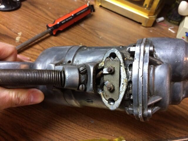 |
| Access panel removed–the two small nuts are connecting the wires in the cord to the drill |
Step 2: Using the diode tester on your multimeter check the cord for shorts.
You can also simply test the resistance of the wires too (which should be nearly zero ohms), to see if the circuit is open. Connect one lead of the multimeter to one of the plugs and then touch the other lead to both of the terminals you just uncovered (one terminal at a time though). The diode tester function of the Fluke 177 True RMS Digital Multimeter with Backlight is very nice because it gives you an audible notification (beep) if the circuit is complete and is silent while there is an open circuit.
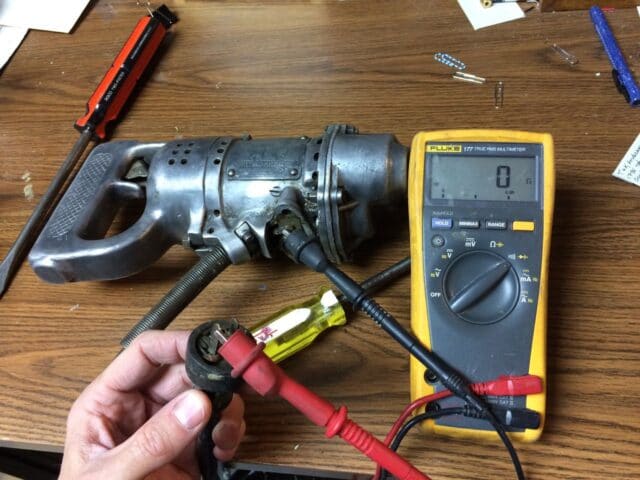 |
| Using the diode tester feature on one of the two wires on the cord for a short–it passed the test |
Neither of the wires on the cord amazingly had shorts! Despite how it looked, the cord was still good. This goes to show that you cannot determine what is wrong with something just by looking at it. And when someone comes to you and tells you that a particular thing is wrong with something you cannot assume that’s what is wrong and try fixing it that way! My second guess is that the trigger switch was bad. Let’s keep chugging along and check the switch.
Step 3: Remove the three screws from the panel on the handle grip.
This is how you access the switch. There is one screw on the right (top) end (the longer one) and two on the other (shorter ones):
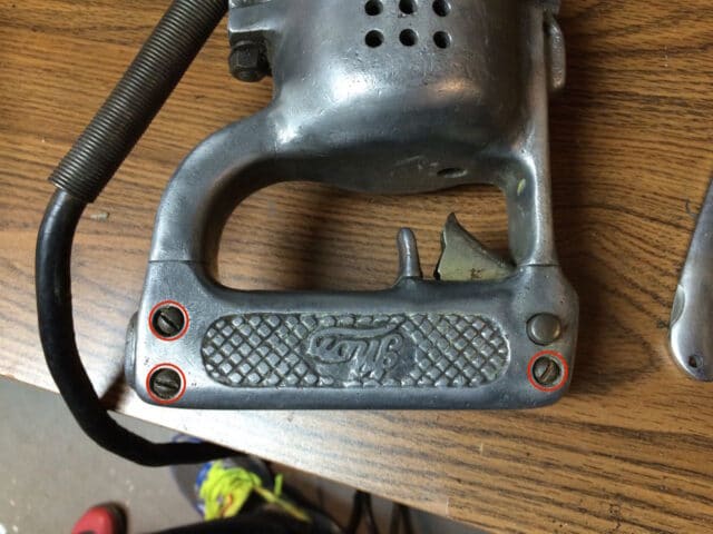 |
| Screw locations on the handle grip |
Make sure to clean out the slots in the screw heads before you attempt to loosen them. If your screw driver is not down in the screw head it might tear up the screw.
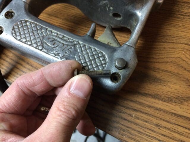 |
| One long screw on the right side |
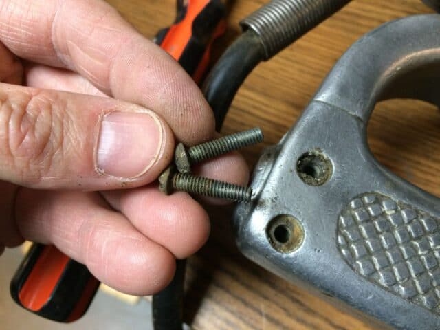 |
| Two shorter screws on the left side |
Remove the handle grip panel. I had to pry it off a bit with my pocket knife in the seam. Here’s what you’ll see when you get it off, the switch:
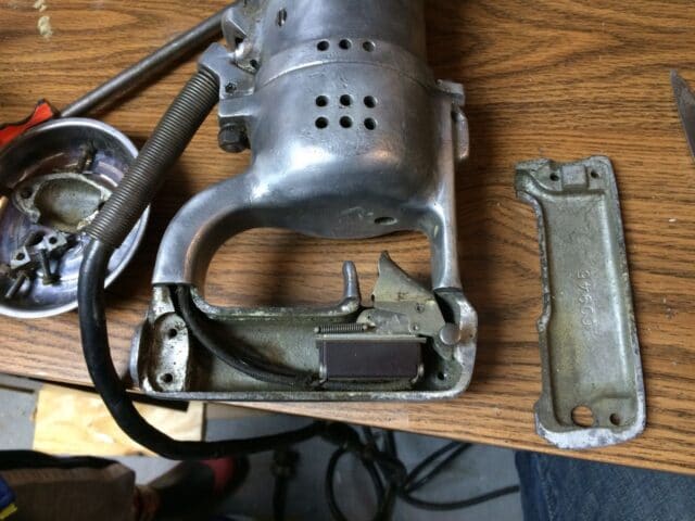 |
| With the handle grip removed you have easy access to the switch |
Before I went any further I wanted to label the wiring so I knew for sure how to put it back together. I only labeled one of the short wires and one of the long ones. I would mention that if you use a black fine-point sharpie like I did, it may rub off the plastic so you might consider scratching your letters into the plastic switch housing or by some other means. Luckily there was a star imprinted on one side of the switch housing that showed me which way it was oriented (but I had to look back at the pictures I had taken to figure it out).
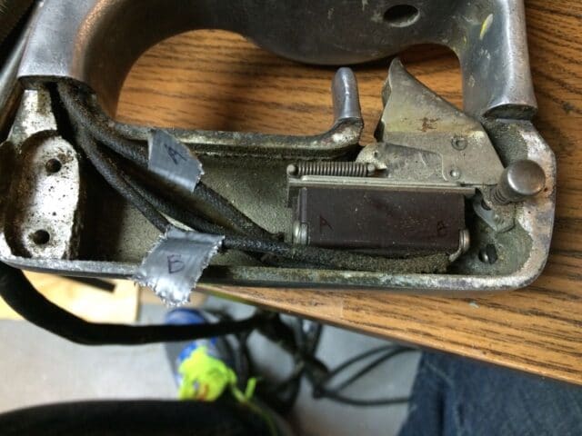 |
| Switch Wiring Labeled |
Step 4: Test the switch.
I didn’t have a clue what was happening inside that switch when I first tore into this but it’s your lucky day because I can now tell you all about what is happening. This is what is called a “double pole, single throw switch” (DPST), for more information read this article on wikipedia. It doesn’t look like this on the inside but this is the symbol for a DPST switch, from wikipedia:
 |
| Symbol for a Double-Pole, Single Throw switch |
The switch connects the wire on one end to/from the wire straight across from it on the other end. I tested those connections (again using the diode tester setting on my Fluke Multimeter) but nothing happened when I squeezed the trigger. The switch is bad!! I decided to see if I could fix it. If this was a modern drill there would be no way to service the switch–you would have to order a part or replace the entire drill but back in the day this drill was made you possibly could take it apart and fix it. Let’s find out…
Step 5: Remove the switch from the drill.
There are two screws on the switch end of the handle:
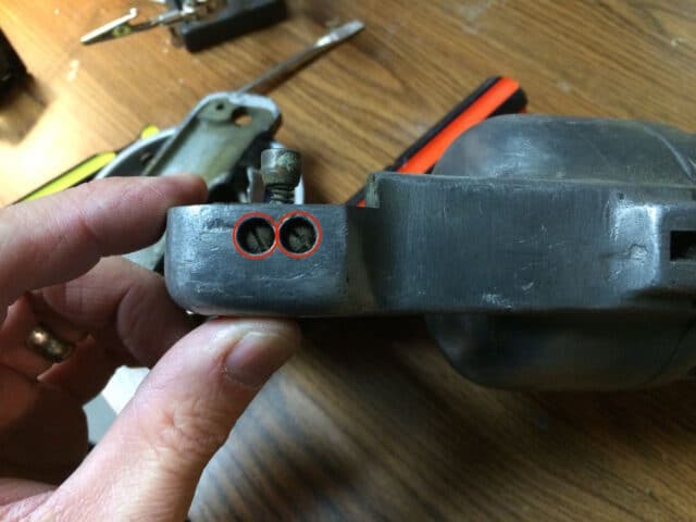 |
| Screw locations for the switch |
After you remove the two screws from the metal case you can lift the switch out of the body of the drill. I put the screws right back into the switch for safe keeping:
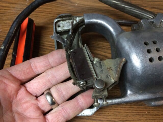 |
| Switch removed and the switch screws put back in their holes |
Go ahead and remove the four screws that connect the wires. This is what you’ll have:
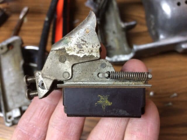 |
| Switch removed |
Step 6: Take the switch apart.
It wasn’t immediately apparent how this switch comes apart but after further inspection I noticed that there were what appeared to be the ends of two screws poking through the metal side of the switch body:
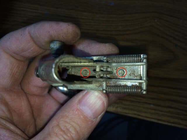 |
| Ends of what looks like screws |
On the other side of the case, lining right up with those screw ends were two mounds of material that looked slightly different than the (most likely Bakelite) plastic of the switch body:
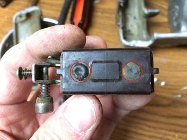 |
| Maybe the screw heads are covered up? |
I took my pocket knife and began to dig and this is what I found, the heads of two screws:
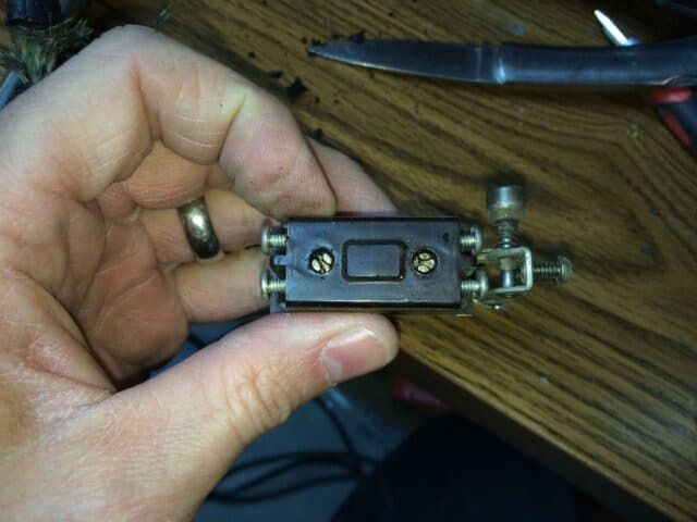 |
| The screw heads revealed that hold the case |
Before you go any farther I would recommend reinstalling the screws that held the wires in place like you see in the picture above. The terminals inside are actually held in place by those screws and this switch is complicated enough–you don’t want to have extra parts flying out of the switch when you open it up if you can help it.
Once you remove those two screws the trigger mechanism will come off and this is what you’ll have. Don’t sweat it if your parts get mixed up, I’ll tell you how to reassemble it later.
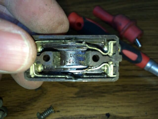 |
| Switch Cover and the metal contact strips that connect to the wires |
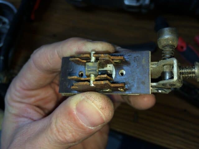 |
| The switching mechanism–kind of complicated |
The way this switch works is that when you pull the trigger it rocks the middle shaft with a spring on it and slides the two outside plates left or right and either connects the right and left connections or disconnects them. The real cause of this switch’s failure is the gunk built up on the contacts as seen below:
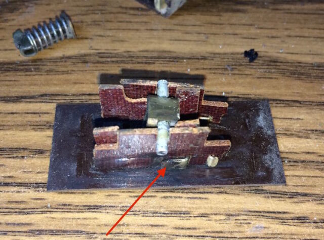 |
| A black tar-like substance built up on the contact |
Step 7: Clean the electrical contacts.
I did a combination of using some Electronics Cleaner I had laying around, scratching the surfaces with my pocket knife, and sanding the surfaces with some 200-grit sandpaper I had laying around. The two outside plates have tabs on both sides that are used for electrical connections and then there are the 4 metal tabs connected to where the wires connect on the outside of the switch. If you take the screws out you can remove those tabs for easier cleaning. I used a q-tip soaked in the electronics cleaner. You could probably use plain rubbing alcohol too.
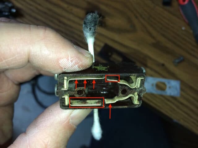 |
| Electrical contact surfaces that need to be cleaned |
I ended up just taking the metal tabs seen above out and rubbing them on 200-grit sandpaper:
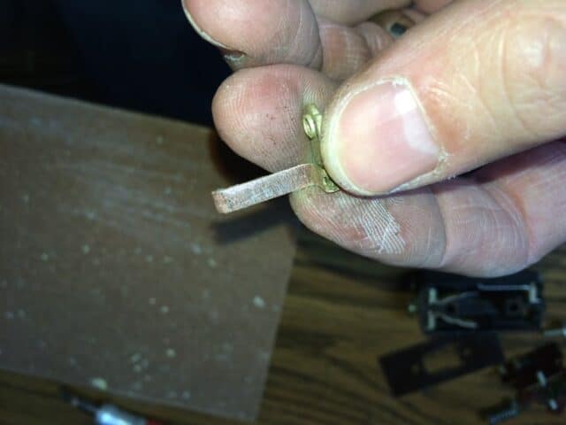 |
| Sanded contacts |
Be careful not to bend them up too much because they are made of copper and will bend easily.
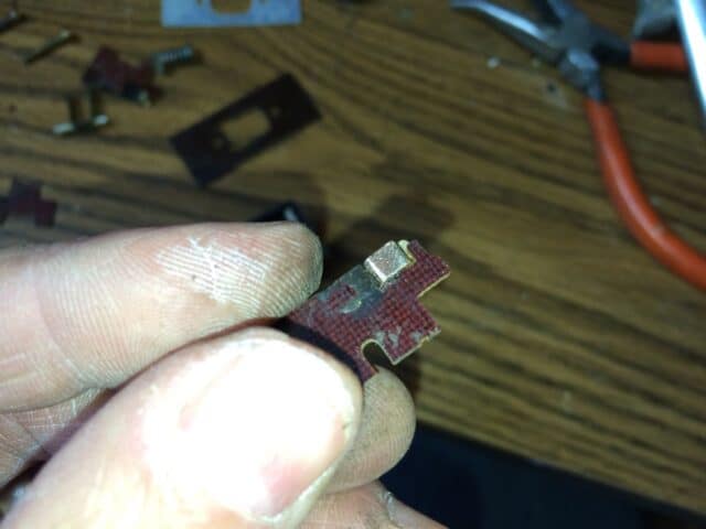 |
| The outside two plates have a surface like seen above on each side of them (you can see I’ve sanded it) |
The copper connecting plate that snakes through the slots of the two inner plates (one pictured above) will come off the plate. I tried to bend it a bit so it fit tightly back onto the plate and wouldn’t fall back off easily. Reassembling this switch is hard enough, you don’t want those plates coming off too easily. I tried cleaning all the tar-like substance off the fiberglass plates as well so it doesn’t end back up on my electrical connections.
Step 8: Re-assemble the switch.
I had to rely on the pictures I took when I disassembled the switch to be able to re-assemble it and even then it still didn’t work. One mistake I made was trying to bend the metal tabs that connect to the wiring so they pressed harder on the contacts of the inner plates (and fit tighter). This actually kept the switch from switching completely. Here is a picture of many of the parts reassembled and labeled (the one main part that is missing is the spring that connects the trigger to the switch.
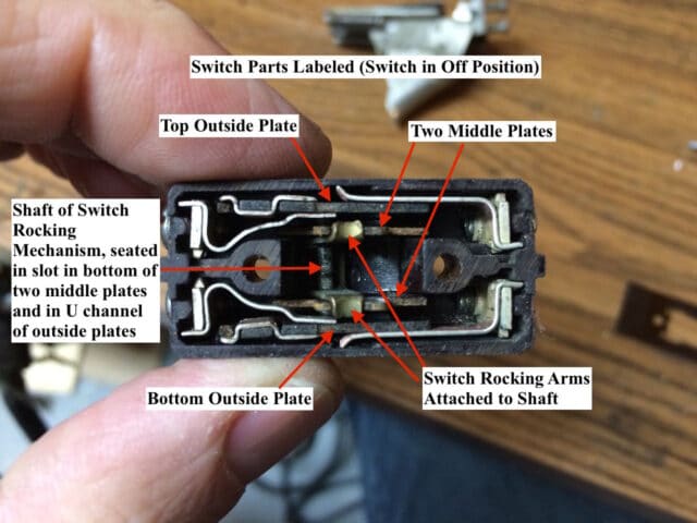 |
| Diagram of the order of the inner parts of the switch |
After you have the parts in the order shown above, you can reinstall the insulating plate. There are two notches in the plate that must be initially aligned with the switch rocking arms. Once you have the insulating plate installed you can slide it so the holes line up as seen below:
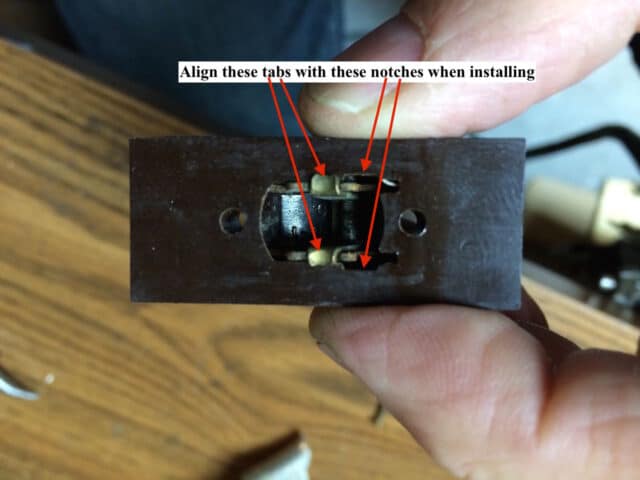 |
| Installing the insulating plate |
Now install the spring connector and the metal plate. The spring connector should rest on the rod that goes through the plates and connects to the rocker arms. When installed this is what it should look like:
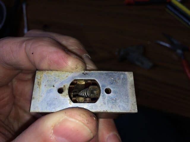 |
| Metal Plate and spring trigger connector installed |
Now place the trigger mechanism on the switch, lining up the arm on the inside of the trigger with the end of the spring connector.
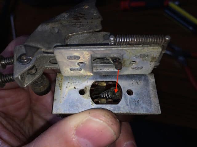 |
| Installing the trigger assembly on the switch–line up as seen above |
Reinstall the two screws we uncovered and removed in step 6. There’s no point in re-covering them, they are fine as is. This is the way it should look with the star on the body of the switch and the trigger on the left side:
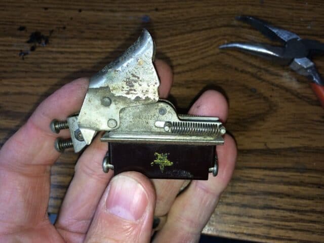 |
| Switch Reassembled |
Step 9: Test the switch.
My switch didn’t work the first or second time I reassembled it. What was happening was that you could pull the trigger but the outer plates of the switch were not sliding back and forth like they should. I had bent the two arms of the swinging assembly out a bit to make it tighter but I undid that (if undid is a word). I also had bent the tabs that connect to the external wiring back so they weren’t pressing so hard on the plates. Here’s how to test your switch:
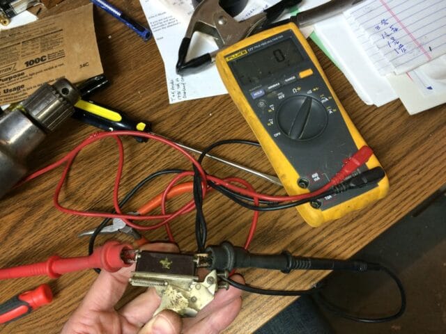 |
| Testing one side of the switch |
Here’s a video of me testing it (when it finally worked) with my Fluke 177 True RMS Digital Multimeter with Backlight:
Once I got one side of the switch working the other side worked too. What is happening as you pull the trigger is that the outer two plates of the switch are sliding from one side to the other, aligning the contacts as to connect the right and left wires:
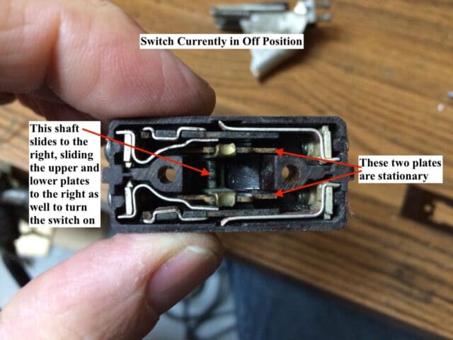 |
| Diagram showing how the switch works |
Once you have the switch working it is time to reinstall it into the drill.
Step 10: Reconnect the four wires to the switch.
Make sure you are connecting the correct wire to each terminal. I labeled mine but the labels wore off the switch body while I was cleaning it. Luckily I had taken pictures and there was a star stamped on the switch body giving me the orientation of the switch:
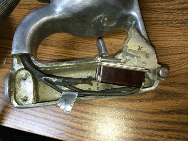 |
| Wires reconnected to the switch |
Step 11: Reinstall the two screws that hold the switch in place.
I didn’t take a picture of this when I was reinstalling them but here’s the original one:
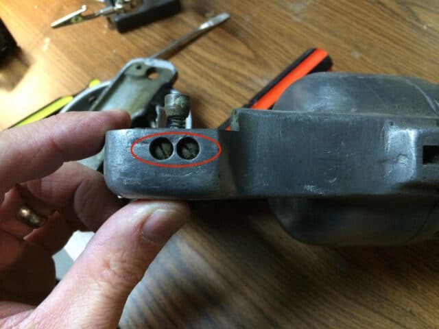 |
| These are the two screws that attach the switch to the drill body |
Step 12: Reinstall the cover plate on the handle.
The long screw goes on the end with only one and the two identical shorter ones go on the other end.
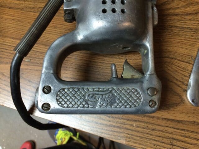 |
| Handle Cover Plate Installed |
Step 13: Remove the cord locking plate.
There is a small plate that squeezes the cord in place. Remove the two flat-head screws:
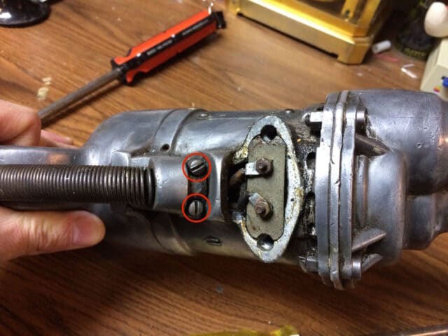 |
| Cord Locking Plate |
Once you’ve removed those two screws you may need to pry the plate loose:
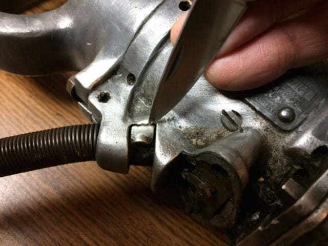 |
| Prying the locking plate free with a pocket knife |
This is what you’ll see when the plate is removed, note the indentation in the cord made by the locking plate, which holds it in place:
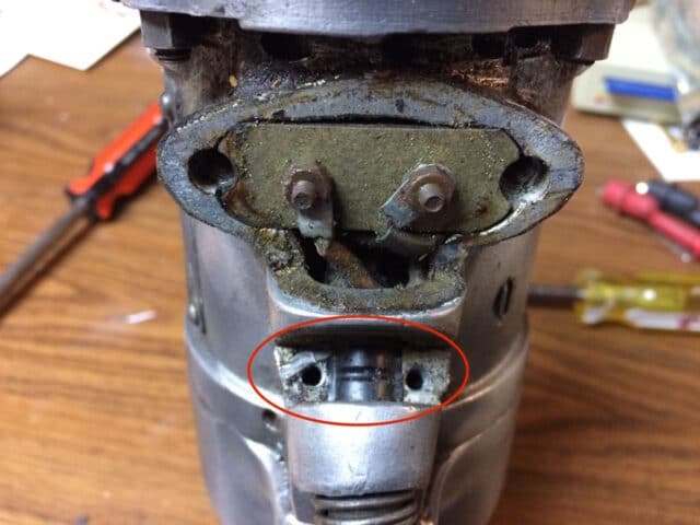 |
| Cord locking plate removed |
Step 14: Remove the two 1/4″ nuts from the two electrical wiring connector.
I used a socket with a screw-driver type handle. Be careful because the insulator that they are bolted to is just sitting in that opening and the motor wiring connects to the back of it and it will jump out of there and twist around on you. If the nut turns, there is a flat head on the other end of the bolt that you can use to hold it still, just be careful to not damage the ancient motor wiring or you will be in trouble. Once you have the nuts off, lift the metal tabs off the bolts.
Step 15: Carefully pull the old cord out.
Pull the cord straight out, being careful that the ends of the wires don’t jump back on the posts they came off of.
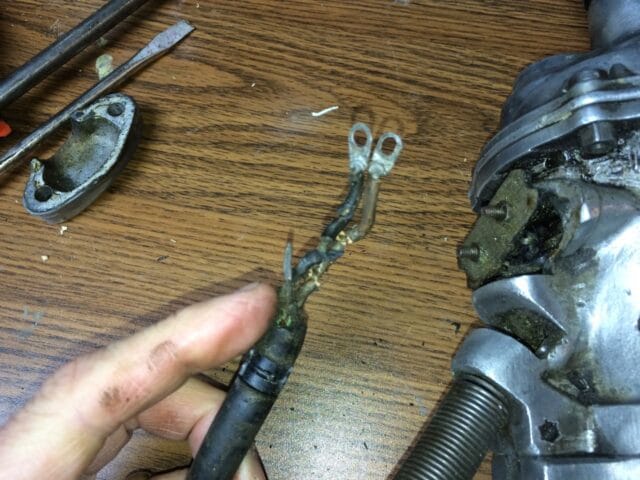 |
| The old cored pulled out |
Step 16: Prepare the end of the new cord.
Strip off plenty of the external insulation. I would not strip any insulation off the ends of the wires until you push the wires through first though or you will run into problems.
Step 17: Push the new cord wires through the spring and into place.
If there are three wires on your cord you’ll need to either cut the ground wire off or figure out a way to connect it to the body of the drill. I opted to cut it off. Make sure the external plastic shielding of the cord is fully visible in the opening where the cord gets “clamped” in place, as seen in the picture below. Before I pulled the cord out to cut off the ground I took this picture of what the wires in place should look like:
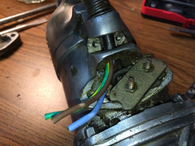 |
| New wires in place |
Step 18: Create wire loops to attach the wires to the posts.
I first cleaned off the insulation. Then I tinned the wires. After you have tinned them bend the wire into a loop and cut off any excess because you don’t really want the wire to overlap in thickness. Re-tin the loop so the solder is completing the circle. I forgot to take detailed pictures of this but if you’ve gone this far I think you can figure that part out.
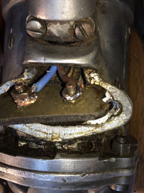 |
| Connecting the new wires |
Here I am holding the bolt in place with a flat-head screwdriver from the back side (be very careful not to damage the wires on the back side):
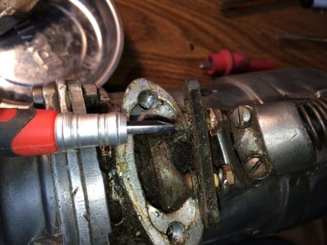 |
| Using a flat-head screw driver to hold the bolt in place |
Step 19: Reinstall the cord locking plate.
You can see that I had already installed it in the two pictures above. Hopefully the cord is thick enough for you so that when you reinstall the plate it clamps it tight. If it is too thin you can mark where it should be clamped, pull it back out, and then wrap enough electrical tape around it to make it thick enough to be clamped down. Now you have a working drill with a cord that isn’t scary:
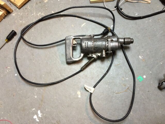 |
| Newly repaired Thor Model 4199 Drill |
Amazon Associate Disclosure: As an Amazon Associate I earn from qualifying purchases. This means if you click on an affiliate link and purchase the item, I will receive an affiliate commission. The price of the item is the same whether it is an affiliate link or not. Regardless, I only recommend products or services I believe will add value to Share Your Repair readers. By using the affiliate links, you are helping support Share Your Repair, and I genuinely appreciate your support.

i used some p b blaster and worked the switch then flushed it with brake cleaner, didn t have electric cleaner, and blew it out and it work ed!! it was intermittent working and now it seems good, springs worry me and lots of parts to get back in right, thanks
WOW, nice how to, i v been working on similar drill and switch and was wondering about taking it apart. hmmm don t know if i m brave enough. springs yeeow! might try spray cleaning and air first
It’s worth a try to use some electronics cleaner on the assembled switch. I sanded the terminal surfaces too, which requires the disassembly–I’m not sure how much that aided in the repair. Check back in and report whether the cleaner only works for you.
I know my husband will love this site! I think every man should have a basic know-how on fixing things, especially if it concerns his household. Know I know where to direct him if he needs tutorials on stuff like these.
Thanks for the comment Camille!
Okay, I'm not gonna lie. I thought coming into this post that I would not be able to relate but after reading this I am now wishing more people out there would post such useful information. Not to mention that my hubby would love this site! (and he doesn't even read but it is useful!) This site is being bookmarked – no doubt
Thank you for your comment Lauren. My site isn't one you would necessarily read every post–most all my visitors find me via a Google search and they happen to have the exact problem I'm solving, but if you like learning how to do things it may be enjoyable since I break it down quite a bit 🙂