If you just got water in your basement because the power went out or because your sump pump failed then you are at the right place. This is the second time I have installed a battery back-up sump pump system and it will help you sleep better at night. It will probably cost you more than $1,000 to hire a plumber to do this but you can do it yourself for about half that. The cost of installing a backup system for your sump pump doesn’t even come close to the cost of replacing all your carpet and the drywall in your basement. Read on to see how easy it really is to do it yourself with my battery backup sump pump installation instructions…
Parts Needed:
- Zoeller 507-0005 Basement Sentry Battery Backup Pump
- 12 V Marine Battery (with threaded terminals on top) — I would just pick up the biggest marine battery they have at your local auto parts store
- Zip Ties
- PVC Cement
Tools Needed:
- cordless drill
- cordless screw driver socket adapter set
- Treble Light with LED bulb (I recommend a treble light with LED bulb so it doesn’t burn out on you when you bump it—I was using my uncles fluorescent light in this repair)
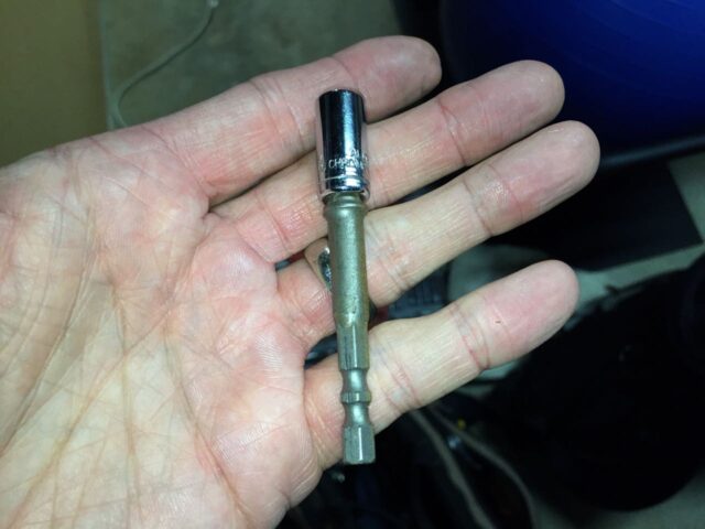
- 5/16 socket (for the pipe clamps) – get this socket and much more in this 170-piece tool set
- Pipe Saw (but most fine-toothed saws will cut pvc)
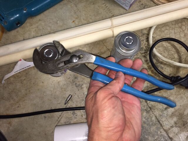
- Channel Lock Pliers (very handy for opening the stuck lids of cans of pvc cement)
- Flush-Cut pliers (for trimming zip ties)
Battery Backup Sump Pump Installation Instructions
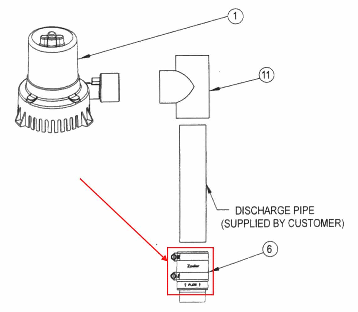
Here is a diagram that gives you an idea of before and after the battery backup sump pump installation:

I will refer to this diagram and the naming of the pvc pipe pieces by the terms mentioned in the diagram above.
Installation Overview
What we are going to do is add an extra pump in line with the current sump pump. To do this we will disconnect “Pipe Piece #1” which is seated into rubber fittings and held by pipe clamps on both ends–seated into the check valve on the bottom and into the flexible coupling on the top. We will cut “Pipe Piece #1” into two pieces. The first piece will be #1A which we will first cement the PVC T-fitting onto it and adjust the height of the backup pump above the main pump. The backup pump will be cemented to the offshoot of the T. Then we will cut the remaining piece of “Pipe Piece #1” into piece #1B which is cut so that it fits within a half inch or so of “Pipe Piece #2”. With the two pipes 1/2″ apart you will be able to slip the flexible fitting back on and connect #1B to #2. The Backup Sump Float assembly can be attached to the pipe anywhere it doesn’t interfere with the main sump pump float or hit something else. The check valve on the outlet of the sump pump keeps the backup sump’s water from going back in the pit. The backup sump pump has its own check valve built into its outlet that keeps the main sump pump’s water from flowing through it. Piece of cake–you can do this and save a lot of money on installation and save tons of stress from worrying about or getting water in your basement.
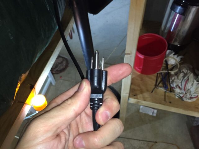
Step 1: Unplug your sump pump.
You don’t want your pump kicking on once you have disconnected its outlet pipe or you will have water everywhere. Unplug your sump pump:
Step 2: Drain the water out of the outlet pipe.
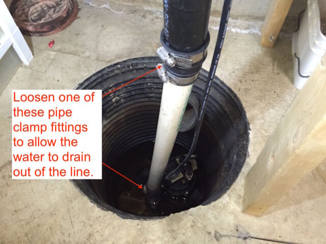
You will have water in the outlet line of your sump pump and that water will be under some amount of pressure since the pipe goes up. Be aware that the water may spray everywhere when you do this. You might have an old towel handy so you can cover the fitting as the water sprays out. I simply just put my hand around the pipe as the water began to spray out. I loosened the top fitting since it was easier to get at but you could loosen the lower one too and it might contain the water better:
Tip: You don’t want to loosen pipe clamps with a flat head screw driver–it will take you forever if you don’t stab into your hand first because the screw driver slipped off the head. Pipe clamps have a 5/16″ hex head on them so use a socket instead. I have an adapter for my cordless screw driver which makes this so easy:
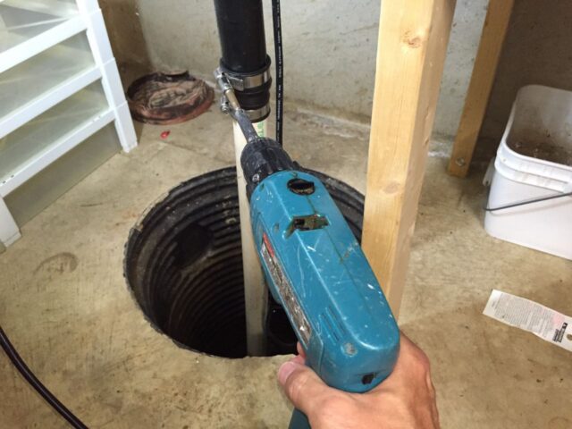
The water squirted up when I loosened the hose clamps (I would have loosened the lower clamp if I did it again, so it would spray down instead):

Step 3: Remove the sump pump from the pit.
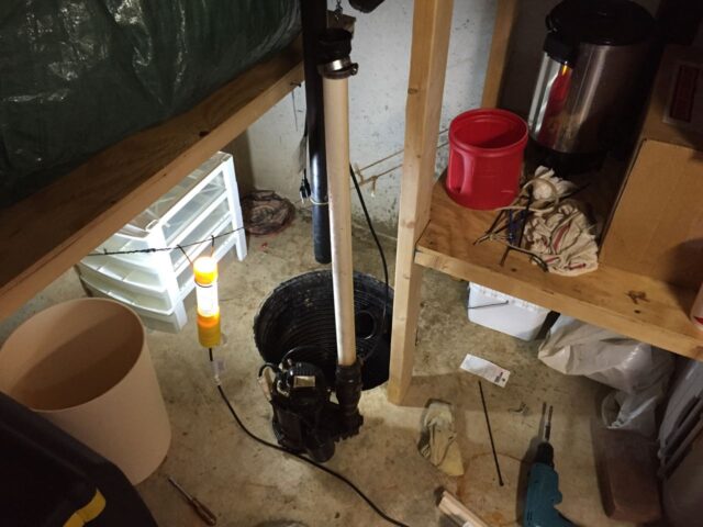
There are multiple different ways you can go about this–disconnecting the pipe from the sump pump or by disconnecting the rubber flexible coupling. I actually tried to pull the white pipe (#1 in my diagram above) up out of the pump (after loosening the lower pipe clamp) but I was unable to pull it out and when I tried to twist the pipe, I could not hold the sump pump from turning because it was stuck in the fitting. So finally I loosened both hose clamps on the flexible fitting and slid the fitting down onto the lower pipe. I then lifted the sump pump up and out of the pit by the handle on the top:
Step 4: Overcome unexpected problems.
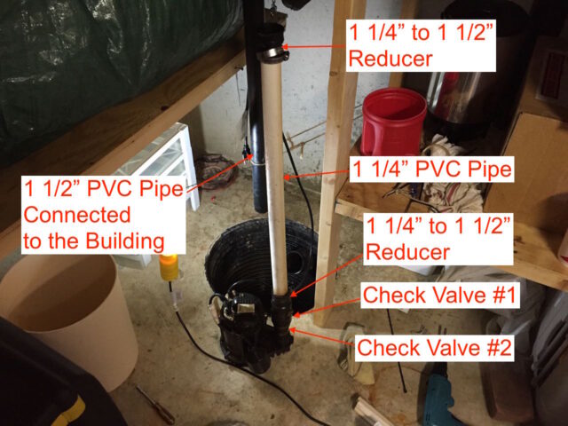
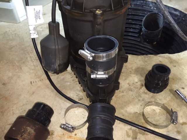
One trick to doing it yourself is overcoming unexpected problems. After I got into this installation I discovered that the pipe coming up out of the pump was 1 1/4″, not 1 1/2″ like the standard size that sump pumps are made for, and the t-fitting that the sump pump connects with, is 1 1/2″ too. I looked for a 1 1/4″ to 1 1/2″ fitting but they are so close together that they don’t sell that size at an average hardware store. Finally I discovered what was going on in this installation–the person who had installed this sump pump had put a reducer coming out of two check valves in series, changing the sump pump’s 1 1/2″ pipe to a 1 1/4″ and then another reducer to step it back up to 1 1/2″ at the flexible fitting at the top to connect it to the building’s 1 1/2″ pipe:
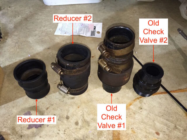
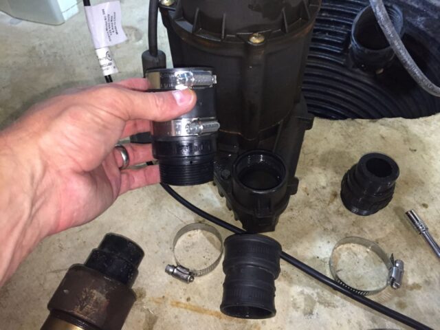
Once I figured out what was going on this installation, I realized that I needed to remove the two reducers so I could use 1 1/2″ pipe, which was necessary to connect the backup pump. I also removed the two check valves and replaced them with the new check valve. Once I figured all that out, purchased a 4′ piece of 1 1/2″ pipe, a 1 1/2″ to 1 1/2″ flexible connection, and was back on track. These were the pieces I took off:
Step 5: Cement the backup pump on the T-fitting.
Now is a good time to go ahead and prep the battery backup pump for installation so it has time to dry while we are doing other things. We are going to use pvc cement to permanently connect the backup pump on the pvc t-fitting:
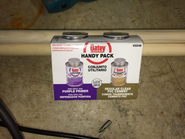
I couldn’t get the caps off these cans by hand and carefully used a pair of channel lock pliers to get them off:
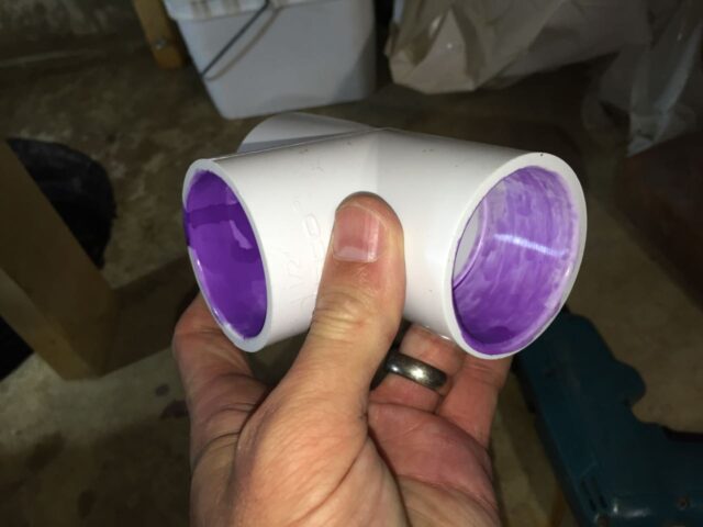
To cement pvc you first prep both surfaces with purple primer. If I were you I would prime all three of the openings of the T-fitting while you are doing the first one:
And the outside of the end of the backup sump pump:
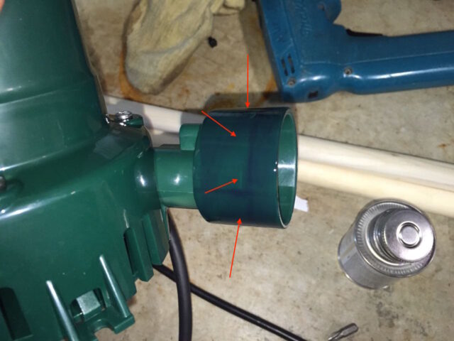
Be careful not to get primer inside the end of the fitting as it could interfere with the built-in check valve on the backup sump pump:
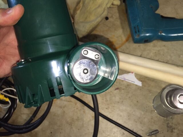
Allow the primer to dry and then apply pvc cement (the clear glue) to the inside of the middle connection on the T-fitting:

Insert the pump into the leg of the T-fitting and turn a quarter turn, lining up the point on the pump with the through branch of the T-fitting as seen below:
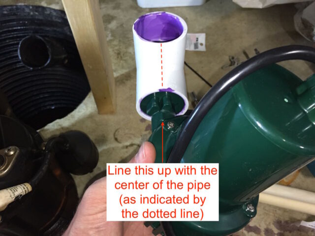
After you insert the pieces together hold them in place for 30 seconds as they will want to push apart until they begin to set. After you hold the pieces in place for 30 seconds set this aside somewhere to dry and be careful that the way you set it doesn’t put pressure on the T-fitting. You should let a cemented pvc joint set for 15 minutes before putting any kind of structural pressure on the joint.
Step 6: Install the new check valve.
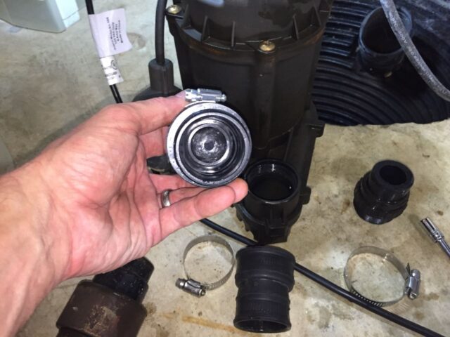
The battery backup pump comes with a new check valve. The check valve keeps the water that remains in the pipe from flowing back into the pump and it also keeps the water that the backup pump pumps from flowing down into the pit instead of up and out. I would suggest going ahead and installing the new check valve while you have the pump out. The check valve slip fits on the pipe on the top end and is threaded on the bottom end and screws down into the the main sump pump.
Here’s a view of the “flap” of the check valve:
Screw the check valve into the sump pump. Hand tight really should be good enough for this low pressure connection:
Step 7: Cut the lower piece of pipe to set the height of the backup sump pump.
Put the pvc pipe (pipe #1) all the way down into the new check valve and holding the newly cemented backup pump and T-fitting determine how long the pipe should be to locate the backup pump above the main pump. You don’t want the backup pump any higher than necessary but you must be careful to not interfere with the main pump’s float. The picture below is actually the original 1 1/4″ pipe that I took out but it illustrates what you need to do:
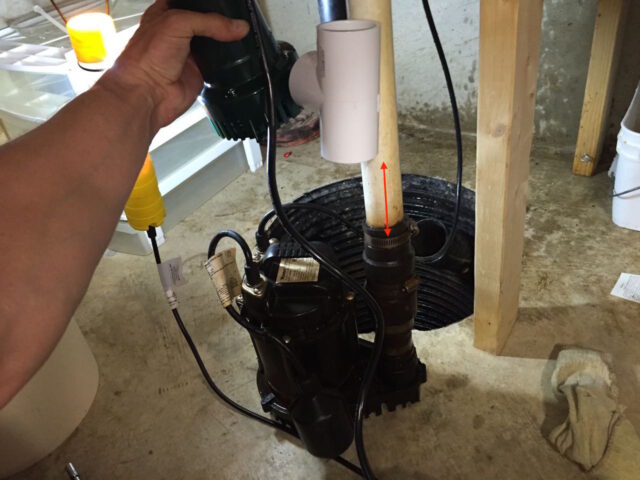
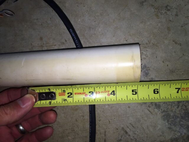
Remember to consider that the pvc will insert into the T-fitting so make sure to add that much to your length. In the picture above I am holding the pump much higher than I ended up mounting it and by the time I mounted it, I had removed the reducer too. The length of this piece is not a super critical measurement–you want the backup sump to be as close above the main pump as possible though, but you could vary quite a bit and it really won’t matter. I went with about a 5″ piece of pipe:
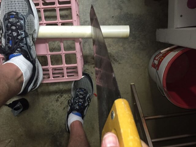
Step 8: Cement the lower pipe piece into the bottom of the T-Fitting.
Prime one end of the piece you just cut:
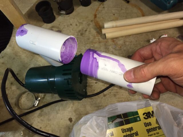
Once the primer is dry, cement the inside of the lower end of the T-Fitting and then fit the pipe into the T-Fitting and hold for 30 seconds to set the pipe:
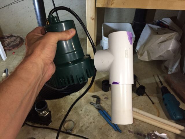
Step 9: Install the backup sump pump into the check valve on the main sump pump.
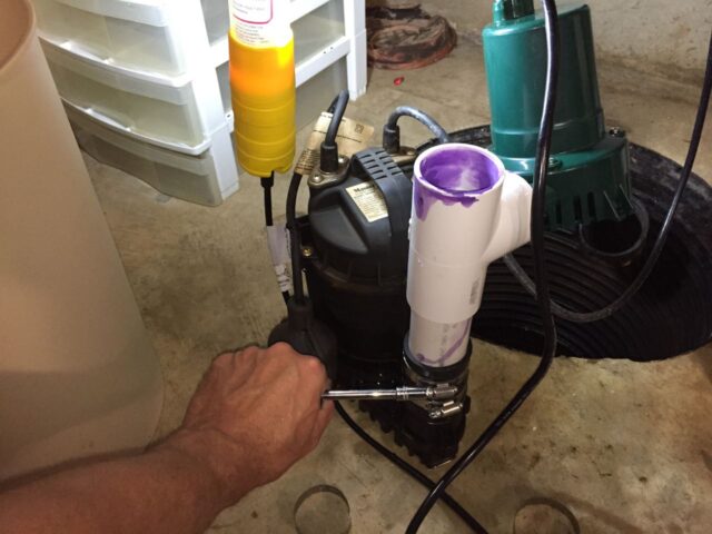
Once you have cemented the pipe as seen above, wait about 15 minutes for the cement to set up and then you can sit it down into the check valve all the way. Make sure you rotate the orientation of the backup pump so that it doesn’t interfere with the float of the main sump pump and then tighten down the pipe clamps:
Step 10: Set the sump pump system down into the pit.
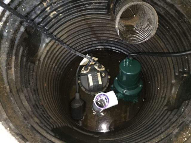
Now that the backup sump pump height is set we can measure the length of pipe needed to run from the flexible fitting that connects to the house’s plumbing to the T-fitting. Set the sump pump down into the pit:
Step 11: Cut the upper pipe piece to connect the sump pump to the main pipe.
You could immediately cement the long piece of pipe you have down into the top of the T-fitting but then you would need to cut the pipe off horizontally, which I did not want to do. So I primed the end of the piece of pipe and pushed it down into the T-fitting and then lined up the pipe with the existing pipe and marked it about 3/4″ to 1″ short of the existing pipe. We are going to install a 1 1/2″ to 1 1/2″ flexible fitting to connect the two pieces so they need not meet up end to end. Line them up and then mark the lower pipe for cutting:
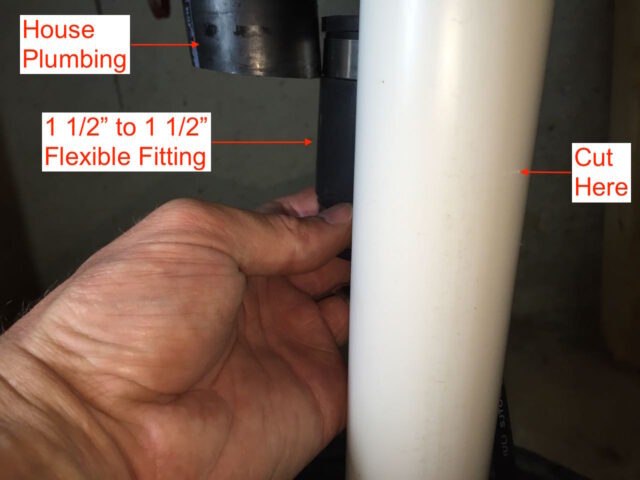
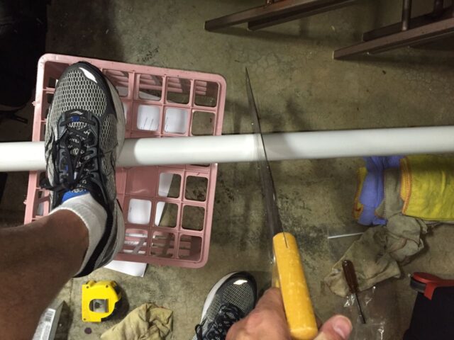
I scratched a line in the pipe with my pocket knife to mark where to cut:
Step 12: Cement the upper pipe piece into the top of the T-Fitting.
Prime the end of the pipe, let it dry, and then cement the pipe into the top of the T-fitting:
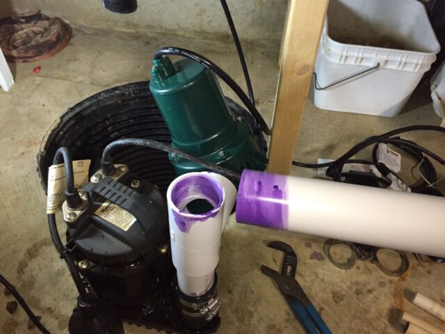
Slip the flexible fitting all the way on the pipe:
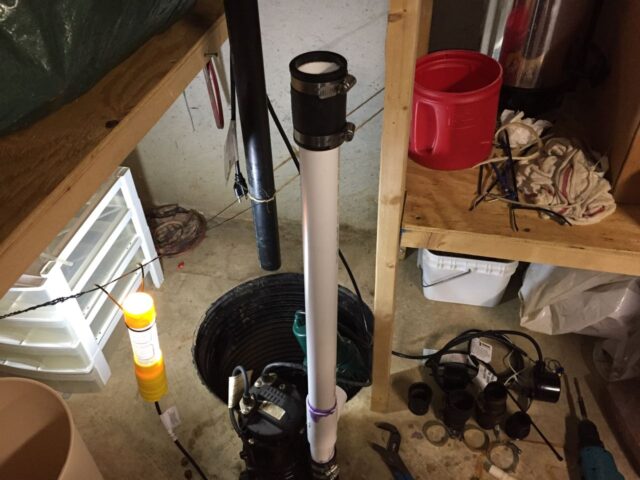
Step 13: Connect the new sump pump system to the main pipe.
Set the sump pump down into the pit. I was tempted to just pick it up by the pipe but felt like that may not be a good idea so I set it down in by the handle on the top of the pump. Position the sump pump so that the main pump float does not get interfered with by the side of the pit or anything else and line up the pipes. Then slide up the flexible fitting to joint the two pipes:
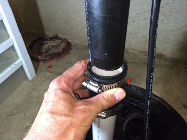
You can squeeze the flexible fitting to get a feel for whether the fitting is centered over the gap. Once you are centered, tighten the two pipe clamps:
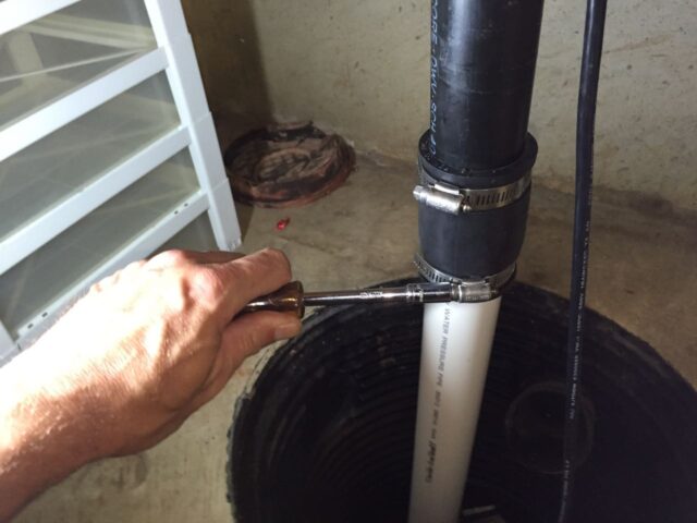
Step 14: Assemble the backup sump pump float system.
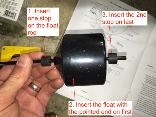
I think it is easiest to install the float on the rod before installing the rod up into the switch. So first slide one of the rubber stops onto the rod, then the float (pointed end first), and then another rubber stop as seen below:
Once you have the float installed you can insert the float assembly into the switch body. It is crucial to orient the rod correctly into the switch body, with the notch on the side with the hole as seen below:
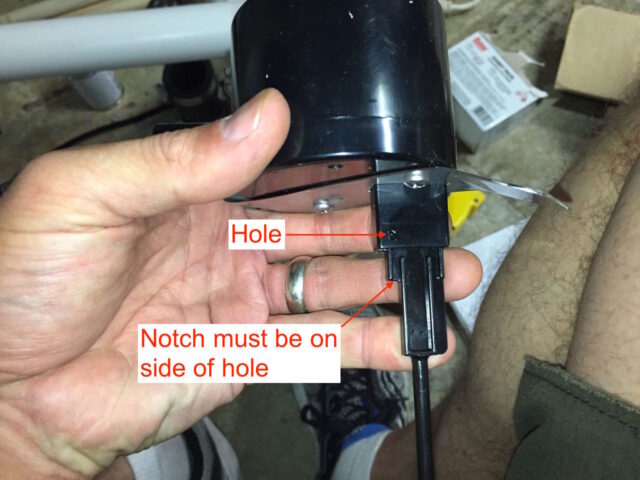
Push the float rod all the way up into the switch body until you can insert a pin into the hole:
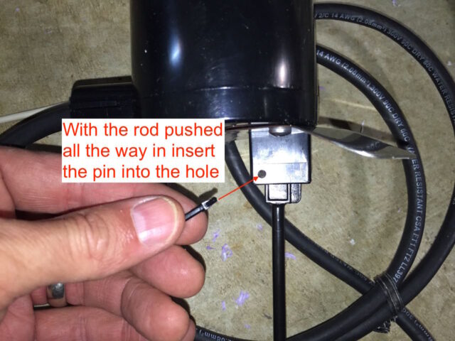
Although the picture below does not show it, I would encourage you to have the two rubber float stops tight up against the float, so there is no play. I scooted them tightly up against the float later but I wanted to mention it now:
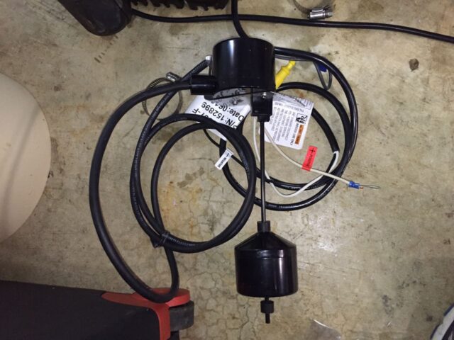
Step 15: Install the backup sump pump float assembly.
The float assembly is secured to the pipe by a metal bracket that has some sharp points that stick out to lock it in place and a pipe clamp holds it tight up on the side of the pipe.

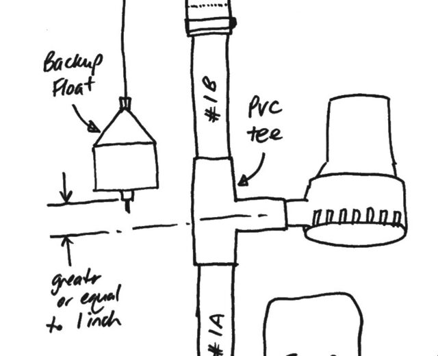
Once you have the pipe clamp started around the pipe then locate the float so that the bottom of the float is 1+inches above the center of the T-fitting (i.e. above the suction of the backup pump):
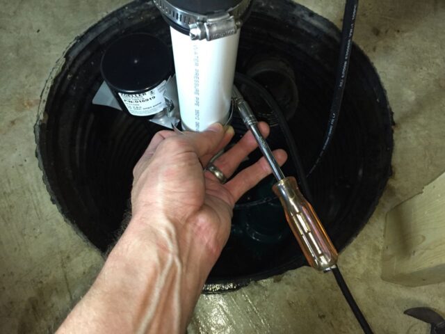
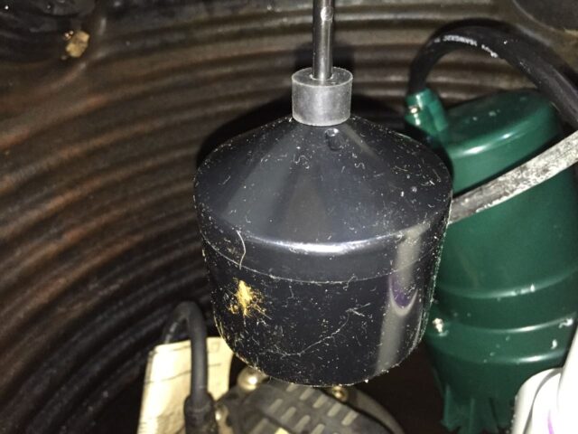
You will need to play around with exactly how to locate the float assembly–you must adjust the height and where it is located around the pipe. Once thing I’ll mention again is that the rubber stop above the float should be tight up against the float (but I don’t believe it is in the picture below):

This is what I mean that the float stops should be tightly placed against the float (so the float doesn’t rise but not move the float switch rod):
Here’s a close up of my initial diagram showing you how the height of the float should be set:
Step 16: Connect the backup sump pump and charger wiring.
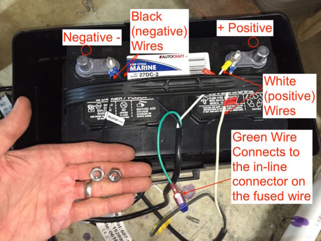
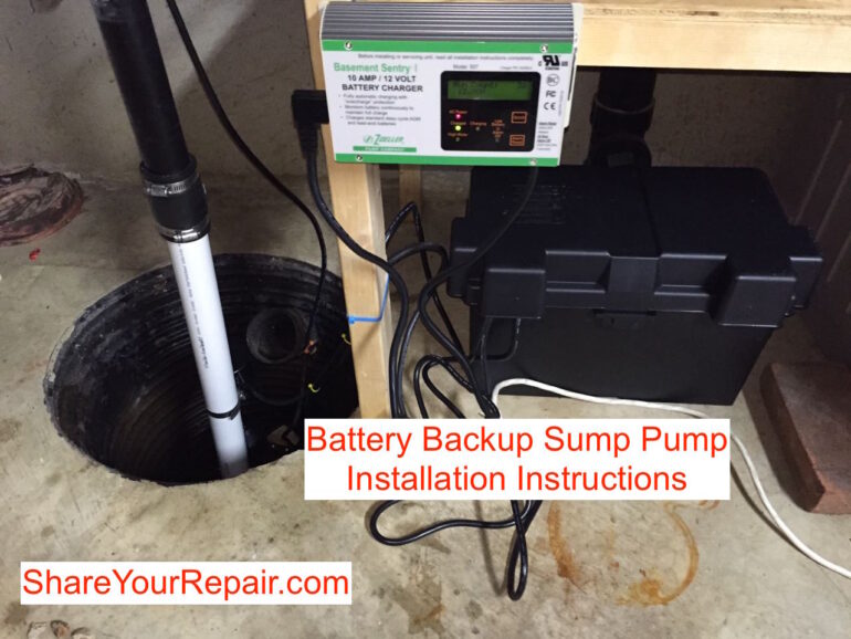
The wires that run from the charger and the float assembly switch all come together and there are multiple connections that need to be made. Refer to the diagram below to connect the float switch, charger, and battery together:
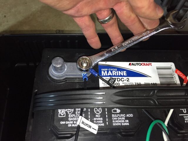
Once you have all the wires connected, install the two nuts on the battery posts and tighten them with a wrench:
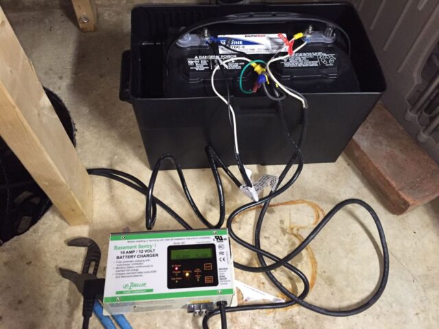
This is what you will have when you are done wiring everything up:
Step 17: Power up the charger.
One important note about powering the backup sump pump charger–it should not be plugged into the same circuit as the main sump pump. This is because if that circuit breaker trips for some reason (if the main pump goes bad) then it cuts the power to the battery backup system too. You will be protected until the battery runs out but you want them to be on separate circuits. You can simply run a heavy extension cord from a distant plug in and test that they are on different circuits by shutting off the sump pump circuit and making sure the battery backup charger still has power.
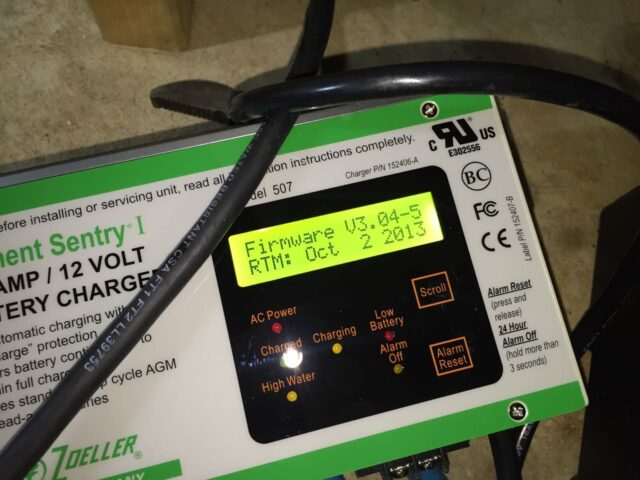
When you first power it up it will tell you the firmware version on the LCD screen:
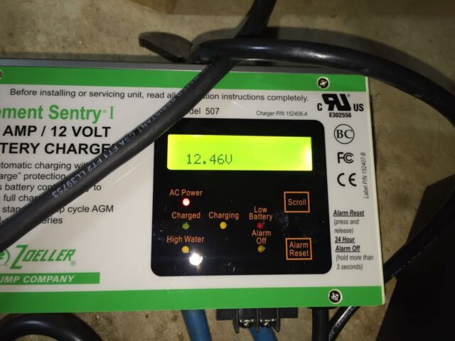
Once it boots up you will see the battery voltage displayed:
Step 18: Mount the charger.
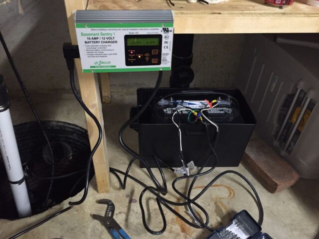
There are tabs on each side of the charger for mounting.
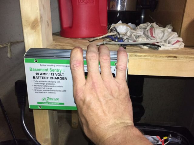
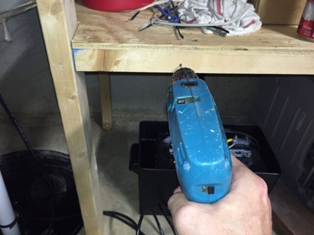
I marked the holes and drilled them first, before installing the screws so I didn’t split the wood:
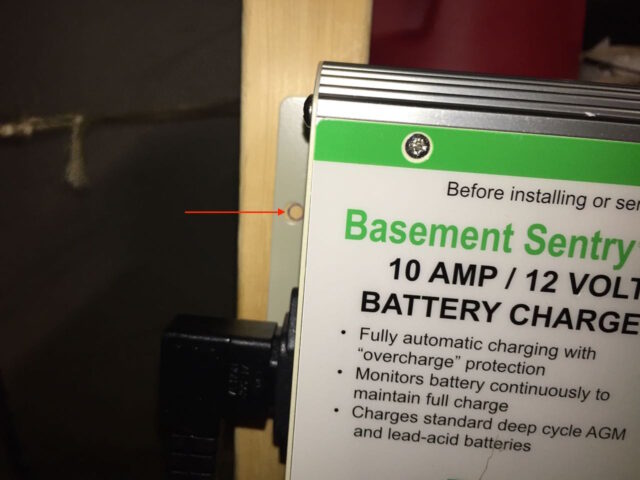
Drilling holes:

Nice and neat (except for the wires, which we will take care of next):
Step 19: Clean up the wiring and close up the battery box.
Fist I used the twist ties that came with the system to secure the wires:
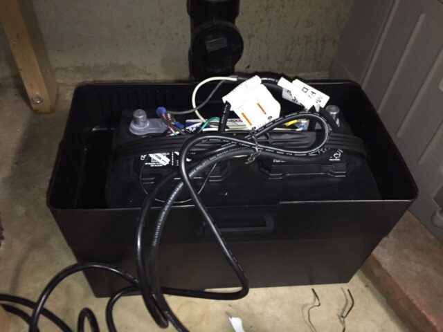
Then snap the lid on the battery box:
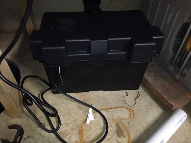
I would have used zip ties to secure the wires that were coming out of the box but I wasn’t sure where the battery was going to be located so I waited to do that.
Secure the wires in the sump pit so they don’t interfere with the floats. This is what mine looked like before cleaning them up:
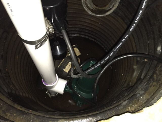
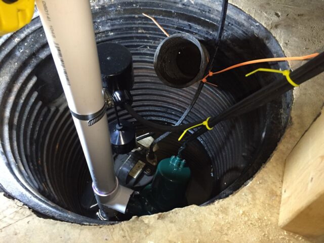
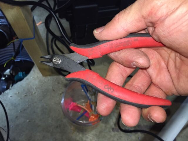
I make things even neater by trimming the zip ties with my flush cut nipper:
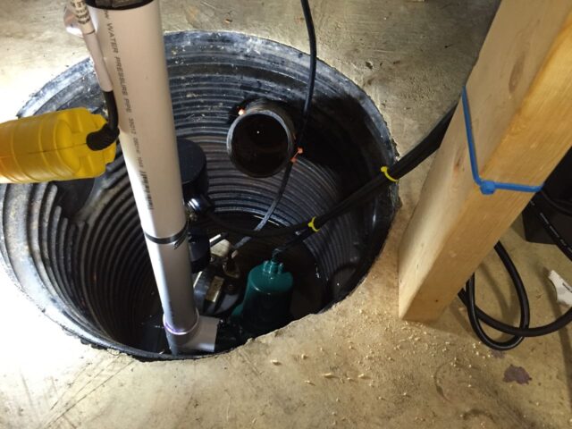
Nice and neat and no worries about wires interfering with floats:
Step 20: Test out your installation.
This is a critical step that you do not want to skip. You could have an issue with your installation and be completely at risk of your backup failing. If you are doing this for someone else like I was you don’t want to leave them thinking they are protected if they really are not, especially when a wet basement is at stake. I ran a hose to the sump pit from a utility sink in the garage:

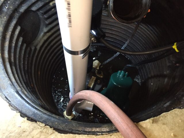
Scenarios to test:
- Normal usage — see that the main sump pump kicks on when it should and empties the pit
- Main sump pump unplugged – see that the backup pump works
- Both main sump pump and backup pump charger unplugged — power out
- Normal usage after a power outage — unplug the main sump pump and let the battery backup pump run a few times, then plug the main pump back in and see that it works OK
Here is a video of me testing it:
I caught that I had positioned the main sump pump too close to the pit wall and the float would hit the wall instead of lifting up with the water level and activating. I also had one test run where the main sump pump kicked on but was not pumping any water–I guess there was air inside the line/pump. Finally the backup pump came on. You want to work through all the different scenarios while you have the hose run to the pit and give it a good run for its money. Then you can relax because you did your job in testing it thoroughly.
Now you can relax when you go out of town or when the power goes out and you saved HUNDREDS by doing it yourself!
Successful with this repair? Do you have a tip to add? Please leave a comment!
If you installed your battery backup sump pump with the help of these instructions please leave a comment and encourage another person to save a lot of money and do it yourself. If you have any tips to share or any input on how to make this tutorial even better, please share and I’ll add your tips.
Please note: if you do not have any approved comments on this site then your comment must be personally approved by me before it will appear. I do this to keep my site 100% free of spam comments. I read them all and almost always review and respond to all comments within a day. I look forward to hearing from you.
Amazon Associate Disclosure: As an Amazon Associate I earn from qualifying purchases. This means if you click on an affiliate link and purchase the item, I will receive an affiliate commission. The price of the item is the same whether it is an affiliate link or not. Regardless, I only recommend products or services I believe will add value to Share Your Repair readers. By using the affiliate links, you are helping support Share Your Repair, and I genuinely appreciate your support.

Thanks. I see the green wire connects to the fuse which connects to… the positive lead? That would explain it. I guess if I’m wrong, it just blows the fuse.
Hi – I had a system installed for a few years, and then one day the Zoeller charger refused to stop charging even though the battery was good and charged. Unfortunately I did not document well enough when I was removing the old Zoeller charger from the circuit and I have the three leads from the pump, and no idea what to do with the fused one. Does it go onto the positive or negative terminal? Thanks…
In step 16 I show a picture with annotations showing where all the connections go and which color wires connect where. I don’t own this house anymore so I can’t look at the installation as a reference.
I cant seem to find the answer to this – is there a test mode for the Zoeller Backup Battery Pumps? Something that can be manually run monthly or so just to make sure everything should work if something were to happen?
The only real way to test Chris, is to unplug the AC power from the pump/Battery recharger and then run or dump water into the pit until the secondary (dc) pump kicks in. And I recommend testing this periodically (yearly).
John, Thanks a lot for your very informative install instructions. I recently hooked up a new Zoeller 507 Sentry 1 battery back-up charger (almost identical to the one in your photos) to a new lead-acid Duracell Ultra size 27 battery. The difference in your 507 and my 507 is that where you have High Water, I have Pump Cycled. Here’s my issue: My 507 is brand new (a replacement for one that went bad), my battery is brand new, and all the wires are hooked up correctly, i. e. negative to negative, positive to positive, and the green wire to the fuse. The solid red Power light shows power, and the Pump Cycled light blinks constantly, even though there has been almost no water entering the sump pump. The yellow Charging light stays on solid, and the Charged light never lights up green (at all), despite constant charging of the new battery (at least 48 hours). The battery has acid. Voltage shows as being in the high 13, low 14 range. The alarm sounds periodically but I can shut it off for 24 hours. Please give me your thoughts. Is there some kind of reset (reboot) maybe? THANKS A LOT!
Since your model is different than the ones I installed that is difficult to guess what is going on. I would contact Zoeller if I were you. I looked them up online and you can email them at zcotechnical@zoeller.com or call them at 800-928-7867. Drop back in and leave a note when you figure out what was going on. Sorry I couldn’t be more help.
Stainless hose clamps come in a wide variety of quality and materials. If Zoeller guarantees their clamps for for 10+ years with 100% submersion, then you can sleep better. A very good test is to check your clamp and screw with a rare earth magnet. If it sticks, you have an inferior clamp (see article below).
I’m commenting here as I had your exact setup and the stainless clamp screw corroded away after being submersed in fresh water for 2 years. When the pump had to run, the pipe separated from the water pressure.
For peace of mind, the fix is easy. Buy ABS or PVC fitting(s) and bond it to the one way valve, and bond a piece of pipe to that. You can place the rubber coupling higher on the pipe above the water line to allow easy disassembly.
I have experience repairing boats in a marine environment as well. Even when not submerged, savvy boat owners will carefully choose their hose clamps from a small subset of clamp suppliers. Even when double clamped, run of the mill stainless clamps corrode and fail all the time.
Here’s a good article about how to find good stainless clamps: http://www.practical-sailor.com/issues/37_16/psadvisory/hose_clamps_10750-1.html
Sorry if I over-explained this.
Best of luck,
…bill
Nice job.
You are using a submerged stainless hose clamp at the check valve on the AC pump. The clamp screw will eventually corrode allowing the pipe to pop off the rubber fitting when the AC pump runs.
This happened to me during a bad rain storm and flooded our basement.
The fix is to use hard ABS or PVC fittings at the check valve and glue/bond the pipe directly to the fittings.
Even though the clamp is stainless steel, the screw may or may not be. Stainless steel can indeed corrode in an oxygen deprived underwater environment. By the way, this happens all the time with stainless fasteners on boats at the water line. My submerged clamp let go after 2 years of being constantly submerged. Best of luck.
Thanks for these write ups,
…bill
Thank Bill for sharing. That’s interesting because the check valve with the two stainless steel hose clamps was provided by the sump pump manufacturer (it even has Zoeller written on the part in the diagram I’m copying below). Maybe I should call the manufacturer and ask them about that.